
A neural network approach to DOA estimation with array errors

A neural network and array error technology, applied in the field of signal processing, can solve problems such as high algorithm complexity, performance degradation, and variation

Active Publication Date: 2019-01-22
SHAANXI SCI TECH UNIV +1
View PDF2 Cites 27 Cited by
  • Summary
  • Abstract
  • Description
  • Claims
  • Application Information

AI Technical Summary

Problems solved by technology

[0002] The high-resolution algorithms for array signal angle of arrival estimation require the array to be in an ideal state, that is, there is no error in the array. performance of subspace-like high-resolution algorithms
Array error has become a bottleneck problem that restricts the performance of signal parameter estimation. For this reason, scholars have proposed a large number of error correction methods, including active error correction and passive error correction. These error correction methods require a known error model, error The modeling of the array is a very complicated process, especially the modeling of the coupling error and the comprehensive error under the existence of multiple errors will be more difficult. When the error model does not match the real error of the array, it will inevitably lead to subsequent Performance degradation of error correction algorithms
The performance of the active error correction method is not only affected by the error model and the accuracy of the signal source parameters. When the signal source parameters are inaccurate, the error estimation performance will also deteriorate. Although the passive correction method does not require known signal source but the complexity of the algorithm is often high

Method used


Image

  • A neural network approach to DOA estimation with array errors
  • A neural network approach to DOA estimation with array errors
  • A neural network approach to DOA estimation with array errors

Examples


Embodiment Construction

[0043] In order to make the above and other objects, features and advantages of the present invention more apparent, the following specifically cites the embodiments of the present invention, together with the accompanying drawings, for a detailed description as follows.

[0044] figure 1 Shown is a schematic diagram of an acoustic pressure sensor array according to an embodiment of the present invention. The ideal array of the present invention is a uniform linear array composed of N sound pressure sensor array elements arranged at equal intervals on the x-axis, and the array element interval is d x , d x ≤0.5λ min ,λ min is the minimum wavelength of the incident signal, but the actual array has position errors due to natural or artificial reasons, such as figure 1 shown.

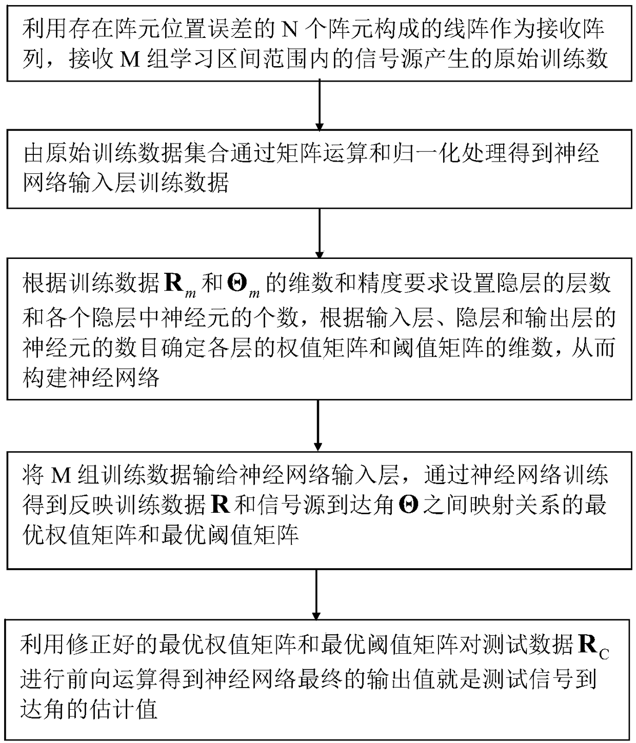
[0045] refer to figure 2 , the steps of the neural network angle-of-arrival estimation method with array errors in the present invention are as follows: the sound pressure sensor linear array receiv...


PUM


Abstract

A linear array composed of N array elements with element position error is used as a receiving array to receive the original training data generated by the signal sources within the range of M groupsof training intervals. The training data of the input layer of the neural network are obtained by matrix operation and normalization from the original training data set. According to the dimension andprecision requirement of training data Rm and signal source arrival angle theta m, the number of hidden layers and the number of neurons in each hidden layer are set, and the dimension of weight matrix and threshold matrix of each layer are determined according to the number of neurons in input layer, hidden layer and output layer, so as to construct a neural network; M groups of training data are input to the input layer of the neural network, and the optimal weight matrix and the optimal threshold matrix reflecting the mapping relationship between the training data R and the angle of arrival of the signal source are obtained through the neural network training. The final output value of the neural network is the estimated value of the angle of arrival of the test signal by using the modified optimal weight matrix and the optimal threshold matrix to carry on the forward operation to the test data RC.

Description

technical field [0001] The invention belongs to the technical field of signal processing, and in particular relates to a neural network method for estimating the arrival angle of a signal source under the condition of an array error. Background technique [0002] The high-resolution algorithms for array signal angle of arrival estimation require the array to be in an ideal state, that is, there is no error in the array. The performance of subspace-like high-resolution algorithms is improved. Array error has become a bottleneck problem that restricts the performance of signal parameter estimation. For this reason, scholars have proposed a large number of error correction methods, including active error correction and passive error correction. These error correction methods require a known error model, error The modeling of the array is a very complicated process, especially the modeling of the coupling error and the comprehensive error under the existence of multiple errors ...

Claims


Application Information

Patent Timeline
Patent Type & Authority Applications(China)
IPC IPC(8): G06K9/00G06N3/04
CPCG06N3/045G06F2218/08
Inventor 王桂宝王翔宇王兰美廖桂生张社民张仲鹏
Owner SHAANXI SCI TECH UNIV
Learn More