cleaning equipment

A technology for cleaning equipment and filter components, applied in cleaning equipment, vacuum cleaners, household appliances, etc., can solve the problems of reduced dust removal efficiency, reduced suction power of vacuum cleaners, blocked air ducts, etc., to improve dust removal effect, improve service life, and reduce operating costs Effect

Active Publication Date: 2021-02-23
JIANGSU MIDEA CLEANING APPLIANCES +1
View PDF7 Cites 0 Cited by
  • Summary
  • Abstract
  • Description
  • Claims
  • Application Information

AI Technical Summary

Problems solved by technology

[0002] After the vacuum cleaner is used for a long time, dust will accumulate on the surface of the filter assembly, which will cause the air duct to be blocked, the suction of the vacuum cleaner will decrease, and the dust removal efficiency will decrease
Moreover, the work of dredging the dust on the surface of the filter component is cumbersome and complicated, which greatly affects the user experience of the vacuum cleaner.
In addition, if the clogged filter assembly is directly replaced, the operating cost of the cleaning equipment and the waste of resources will be increased

Method used


Image

  • cleaning equipment
  • cleaning equipment
  • cleaning equipment

Examples


Embodiment 1

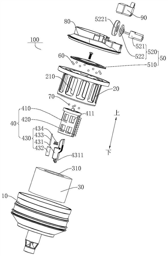
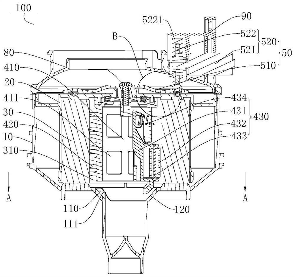
[0081] like Figure 1-Figure 8 , Figure 10-Figure 12 As shown, the cleaning device 100 may be a vacuum cleaner, and the cleaning device 100 includes: a body 10 , a bracket 20 , a filter assembly 30 , a dust removal assembly 40 , a trigger 110 and a drive assembly 50 .

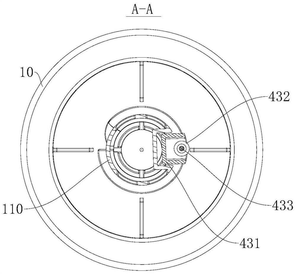
[0082] Among them, such as figure 1 , figure 2 and Figure 12 As shown, there is a dust and gas separation system 130 inside the machine body 10, and the dust and gas separation system 130 can be a single-cone or multi-cone separator for separating and removing dust from the airflow. The dust and gas separation system 130 includes a conical part 120, the cross-sectional area of ​​the conical part 120 gradually decreases in the direction from top to bottom, and a trigger 110 is provided on the inner wall of the conical part 120, and the trigger 110 has a second Match the bevel 111.

[0083] like figure 1 and figure 2 As shown, the bracket 20 is disposed in the body 10. The bracket 20 has an annular out...

Embodiment 2

[0094] like Figure 9 As shown, the difference from Embodiment 1 is that in this embodiment, the driving wheel 522 is a gear, and the driving disc 510 is provided with a rack 511 matching the gear. The cooperation between the gear and the rack 511 can improve the firmness and reliability of the cooperation between the driving wheel 522 and the driving disc 510 . Moreover, the transmission ratio between the drive wheel 522 and the drive disc 510 can be calculated and designed according to the rotation speed requirement of the dust removal assembly 40 , which improves the stability and reliability of the operation of the dust removal assembly 40 .


PUM


Abstract

The invention discloses a cleaning device. The cleaning device includes: a machine body, a filter assembly, a dust removal assembly and a trigger member. The dust removal assembly is rotatably arranged in an air flow channel. It is arranged on the rotating part and is in contact with the inner peripheral wall of the filter assembly. The trigger part is in periodic contact with the dust shaking assembly to make the dust shaking assembly reciprocate within a preset movement distance to beat the inner peripheral wall of the filter assembly. According to the cleaning device of the present invention, the driving assembly can drive the dust removal assembly to rotate in the air flow channel, and the brush can clean and remove dust from the inner peripheral wall of the filter assembly. Moreover, the dust-shaking component is in periodic contact with the trigger, so that the dust-shaking component reciprocates within a preset movement distance to slap the inner peripheral wall of the filter component, thereby shaking off the dust on the filter component and improving the dust removal effect of the dust-removing component , effectively avoiding the problem that dust accumulation blocks the filter components and affects the working efficiency of cleaning equipment.

Description

technical field [0001] The invention relates to the technical field of cleaning appliances, in particular to a cleaning device. Background technique [0002] After the vacuum cleaner is used for a long time, dust will accumulate on the surface of the filter assembly, which will cause the air duct to be blocked, the suction of the vacuum cleaner will decrease, and the dust removal efficiency will decrease. Moreover, the work of dredging the dust on the surface of the filter component is cumbersome and complicated, which greatly affects the user experience of the vacuum cleaner. In addition, if the clogged filter assembly is directly replaced, the operating cost of the cleaning equipment and the waste of resources will be increased. Contents of the invention [0003] The present invention aims to solve at least one of the technical problems existing in the prior art. Therefore, the present invention proposes a cleaning device, the cleaning structure has the advantages of s...

Claims


Application Information

Patent Timeline
Patent Type & Authority Patents(China)
IPC IPC(8): A47L5/12A47L9/10
CPCA47L5/12A47L9/10
Inventor 倪兵兵干一宏王永华
Owner JIANGSU MIDEA CLEANING APPLIANCES
Why Eureka
Try Eureka