
Cylinder seat tinning device for refrigerator

A technology of tin plating device and cylinder block, which is applied in the direction of injection device, etc., can solve the problems of difficult to remove tin, lower efficiency, lower use effect of refrigerators, etc., and achieve the effect of good tin plating effect and high efficiency

Inactive Publication Date: 2019-01-25
黄石市金雀电气股份有限公司
View PDF0 Cites 3 Cited by
  • Summary
  • Abstract
  • Description
  • Claims
  • Application Information

AI Technical Summary

Problems solved by technology

[0002] The surface of the cylinder block used in refrigerators is often tinned before use to ensure that the surface of the cylinder block will not be corroded due to external factors during use, which will reduce the use effect of the refrigerator. The existing cylinder block is sprayed and plated When tinning, all surfaces of the cylinder block need to be sprayed. During the spraying process, the cylinder block needs to be rotated and sprayed continuously. Due to the continuous rotation, the efficiency of the cylinder block during tinning is reduced, and the spraying of tinned Some tin will inevitably be sprayed on the workbench, which makes it difficult to remove the tin sprayed on the workbench. Therefore, we propose a tinning device for cylinder blocks used in refrigerators.

Method used


Image

  • Cylinder seat tinning device for refrigerator
  • Cylinder seat tinning device for refrigerator

Examples


Embodiment Construction

[0014] The following will clearly and completely describe the technical solutions in the embodiments of the present invention with reference to the accompanying drawings in the embodiments of the present invention. Obviously, the described embodiments are only some, not all, embodiments of the present invention.

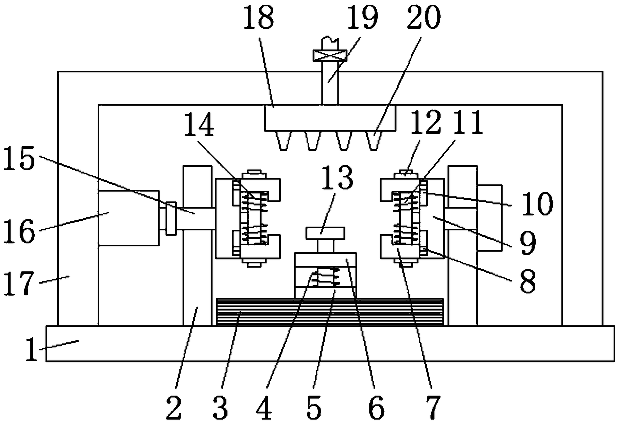
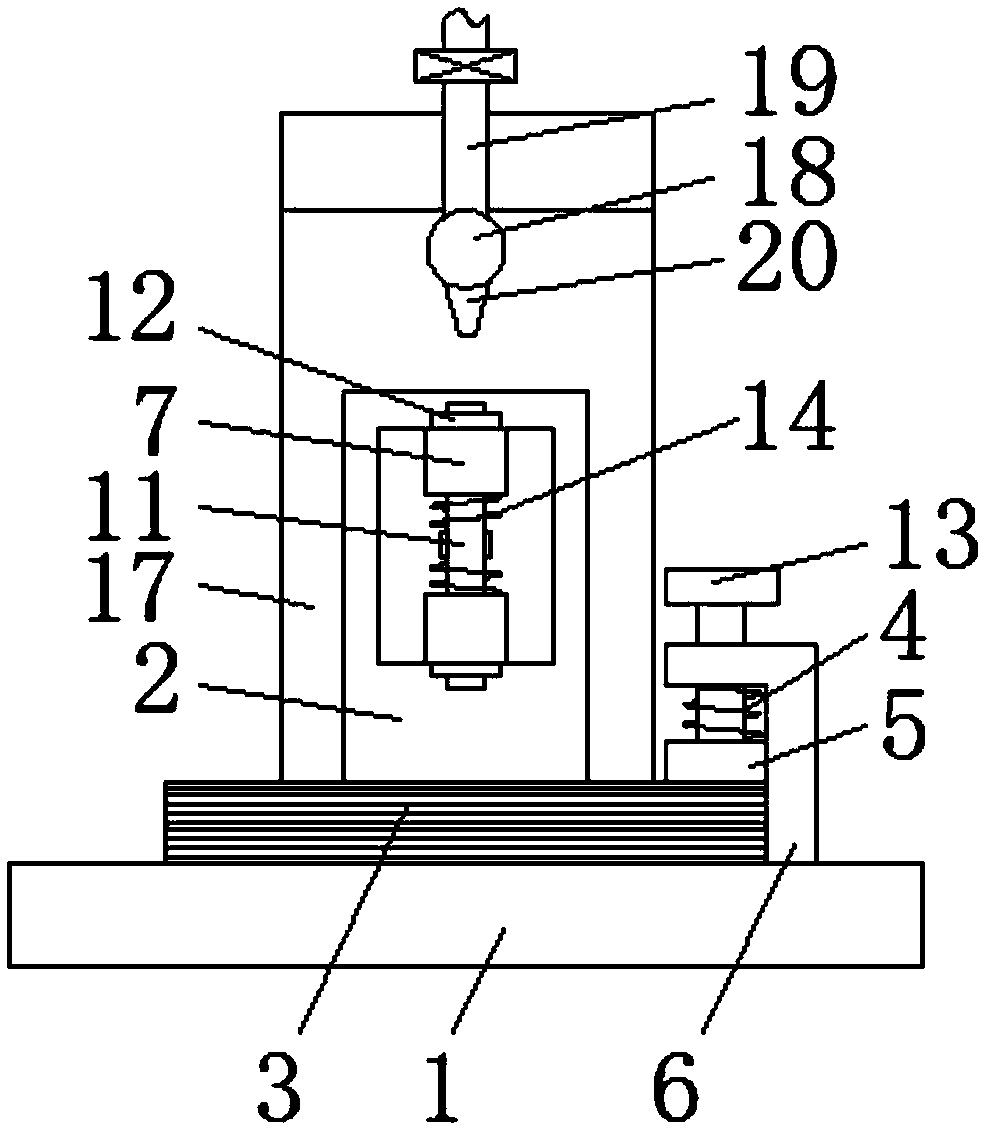
[0015] refer to Figure 1-2 , a cylinder seat tinning device for a refrigerator, comprising a workbench 1, vertical support plates 2 are fixed at both ends of the upper side of the workbench 1, and horizontal rotating shafts 15 are arranged on the two support plates 2, and the two rotating shafts 15 is fixed on the corresponding side with a rotating plate 9, and the center of the corresponding side of the two rotating plates 9 is welded with a threaded rod 11 through a connecting rod, and the upper and lower ends of the corresponding side of the two rotating plates 9 are provided with L-shaped splint 7, and the two ends of the threaded rod 11 respectively run through...


PUM


Abstract

The invention relates to the technical field of tinning devices, in particular to a cylinder seat tinning device for a refrigerator. Support plates are fixed at both ends on the upper side of a workbench, and the two support plates are respectively provided with a rotating shaft in the penetration mode. The corresponding sides of the two rotating shafts are respectively fixedly provided with a rotating plate, and the corresponding sides of the two rotating plates are respectively provided with a threaded rod by welding through a connecting rod. The upper and the lower ends of the correspondingsides of the two rotating plates are respectively provided with an L-shaped clamping plate through a sliding mechanism, and the two ends of the threaded rods respectively penetrate the two L-shaped clamping plates. The outsides of the upper and lower ends of the two threaded rods are respectively provided with a knob, a U-shaped frame is fixed on the upper end of the workbench, a motor is mountedon the inner side of the U-shaped frame, an output shaft of the motor is connected with one rotating shaft, and the other end of the other rotating shaft is fixedly provided with a limiting block. Aconnecting pipe is fixed on the upper side of the U-shaped frame, and a plurality of nozzles are evenly arranged at the lower end of the connecting pipe, and a feeding pipe with a valve is connected to the upper end of the connecting pipe. The tinning device is simple in structure and high in tinning efficiency and causes no pollution to the workbench.

Description

technical field [0001] The invention relates to the technical field of tinning devices, in particular to a tinning device for a cylinder seat of a refrigerator. Background technique [0002] The surface of the cylinder block used in refrigerators is often tinned before use to ensure that the surface of the cylinder block will not be corroded due to external factors during use, which will reduce the use effect of the refrigerator. The existing cylinder block is sprayed and plated When tinning, all surfaces of the cylinder block need to be sprayed. During the spraying process, the cylinder block needs to be rotated and sprayed continuously. Due to the continuous rotation, the efficiency of the cylinder block during tinning is reduced, and the spraying of tinned During the process, some tin will inevitably be sprayed on the workbench, making it difficult to remove the tin sprayed on the workbench. Therefore, we propose a tinning device for cylinder blocks used in refrigerators....

Claims


Application Information

Patent Timeline
Patent Type & Authority Applications(China)
IPC IPC(8): B05B13/02B05B14/00
CPCB05B13/0228B05B13/0278B05B14/00
Inventor 金敏
Owner 黄石市金雀电气股份有限公司
Learn More