
Efficient water pollution control equipment

A water pollution and high-efficiency technology, applied in the direction of presses, manufacturing tools, etc., can solve the difficulty of storage and transportation of high-efficiency water pollution control equipment, reduce the practicability of high-efficiency water pollution control equipment, and the high-efficiency water pollution control equipment has a large volume and other problems, to achieve the effect of improving convenience, simple structure and reducing quantity

Inactive Publication Date: 2019-01-25
陈兴颖
View PDF0 Cites 0 Cited by
  • Summary
  • Abstract
  • Description
  • Claims
  • Application Information

AI Technical Summary

Problems solved by technology

[0003] As a kind of environmental protection equipment, high-efficiency water pollution control equipment is widely used in the process of treating water surface garbage. Generally, when high-efficiency water pollution control equipment is dealing with water surface garbage, in order to improve the processing efficiency, high-efficiency water pollution control The large size of the equipment makes it difficult to store and transport high-efficiency water pollution control equipment, thereby reducing the practicability of high-efficiency water pollution control equipment. Not only that, but the capacity of general high-efficiency water pollution control equipment is limited, which leads to high-efficiency water pollution control equipment. Water pollution control equipment intelligently accommodates a limited amount of water surface garbage, thereby further reducing the practicability of efficient water pollution control equipment

Method used


Image

  • Efficient water pollution control equipment
  • Efficient water pollution control equipment
  • Efficient water pollution control equipment

Examples


Embodiment Construction

[0025] The present invention is described in further detail now in conjunction with accompanying drawing. These drawings are all simplified schematic diagrams, which only illustrate the basic structure of the present invention in a schematic manner, so they only show the configurations related to the present invention.

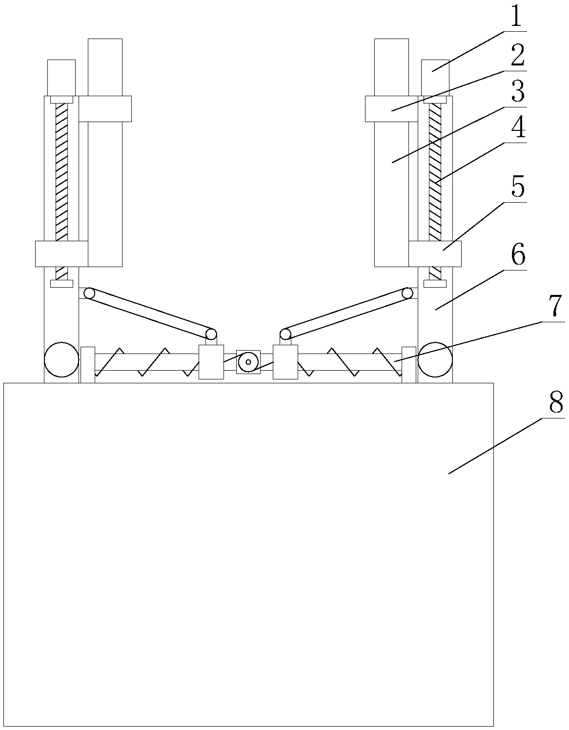
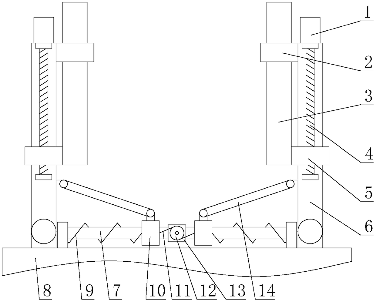
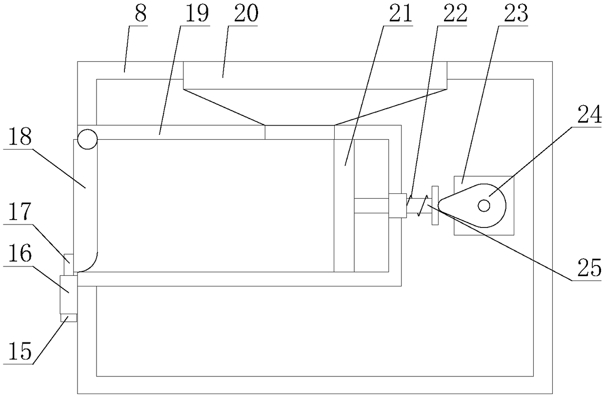
[0026] Such as figure 1 As shown, a high-efficiency water pollution control equipment includes a main body 8, and also includes a collection mechanism and a storage mechanism, the collection mechanism is arranged on one side of the main body 8, and the storage mechanism is arranged inside the main body 8;

[0027] Such as figure 2 As shown, the collection mechanism includes a first drive assembly, a transmission assembly and two collection assemblies, the two collection assemblies are respectively arranged at both ends of one side of the main body 8, and the transmission assembly is arranged between the two collection assemblies, The first driving assembly ...


PUM


Abstract

The invention relates to efficient water pollution control equipment. The efficient water pollution control equipment comprises a main body, and further comprises a collecting mechanism and a storagemechanism, wherein the collecting mechanism comprises a first driving assembly, a transmission assembly and two collecting assemblies; each collecting assembly comprises a rotating rod, a driving unit, a driving sleeve, a reinforcing sleeve, a movable rod and two collecting plates; the storage mechanism comprises a locking assembly, a second driving assembly, a feeding opening, a collecting groove, a cover plate, a push plate, a second spring and a second transmission rod; and the transmission assembly comprises a guiding rod, two sliding sleeves, two first springs and two first transmission rods. In the efficient water pollution control equipment, the collecting mechanism drives the two rotating rods to rotate, and meanwhile drives the movable rod to move along the rotating rods, therefore, the control range of the control equipment is expanded, the working efficiency of the control equipment is improved, the storage mechanism drives a push plate to move in the left-right direction ina reciprocating manner, garbage is compressed through the push plate, and the garbage capacity of the control equipment is increased.

Description

technical field [0001] The invention relates to the field of water pollution treatment equipment, in particular to a high-efficiency water pollution treatment equipment. Background technique [0002] Environmental protection equipment refers to mechanical products, structures and systems manufactured and constructed by production units or construction installation units for controlling environmental pollution and improving environmental quality. Some people also think that environmental protection equipment refers to mechanically processed products to control environmental pollution, such as dust collectors, welding fume purifiers, monomer water treatment equipment, noise controllers, etc. This understanding is not comprehensive. Environmental protection equipment should also include power equipment for transporting pollutant-containing fluid substances, such as water pumps, fans, conveyors, etc.; it also includes monitoring and control instruments to ensure the normal oper...

Claims


Application Information

Patent Timeline
Patent Type & Authority Applications(China)
IPC IPC(8): B30B9/30B30B15/00
CPCB30B9/30B30B9/3003B30B9/305
Inventor 陈兴颖
Owner 陈兴颖
Learn More