
A prefabricated beam slab and its construction method

A construction method and prefabricated technology, applied in the processing of building materials, construction, building components, etc., can solve the problems affecting construction quality and construction progress, the impact of structural stability at joints, and low work efficiency, so as to eliminate concrete The effect of slurry leakage, improving project economic benefits and convenient construction

Active Publication Date: 2020-08-18
天津一冶建设工程有限公司
View PDF6 Cites 0 Cited by
  • Summary
  • Abstract
  • Description
  • Claims
  • Application Information

AI Technical Summary

Problems solved by technology

The work efficiency of the traditional method is low, and the steel bars are prone to misalignment and grout leakage during concrete pouring, which has a great impact on the quality of concrete molding and the structural stability of joints
There is no technology that can solve this problem well in the prior art, which greatly affects the construction quality and construction progress

Method used


Image

  • A prefabricated beam slab and its construction method
  • A prefabricated beam slab and its construction method
  • A prefabricated beam slab and its construction method

Examples


Embodiment Construction

[0033] The present invention is illustrated below in conjunction with the accompanying drawings.

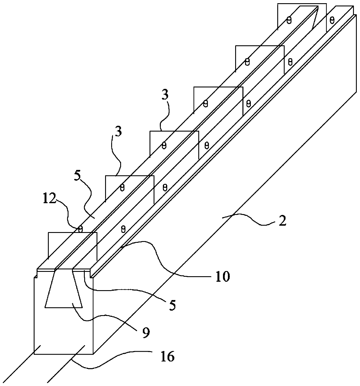
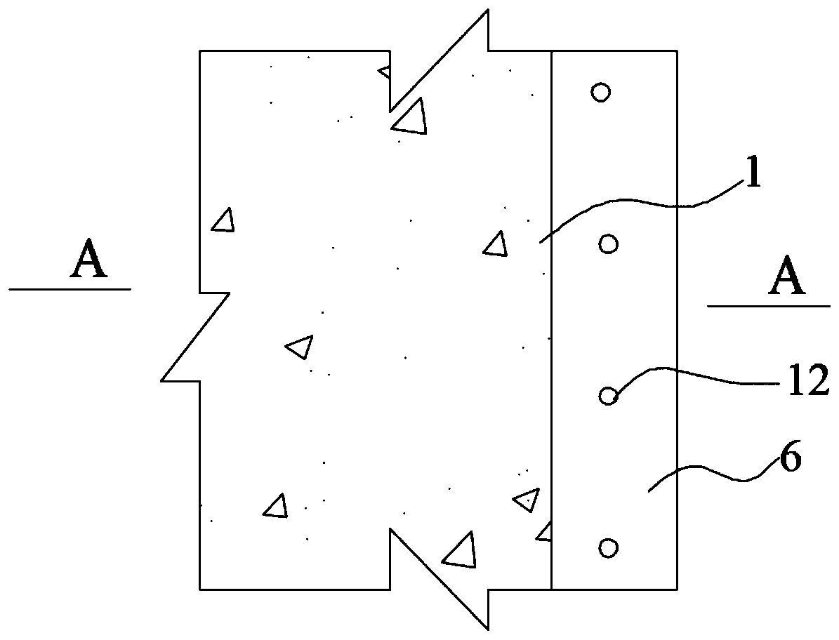
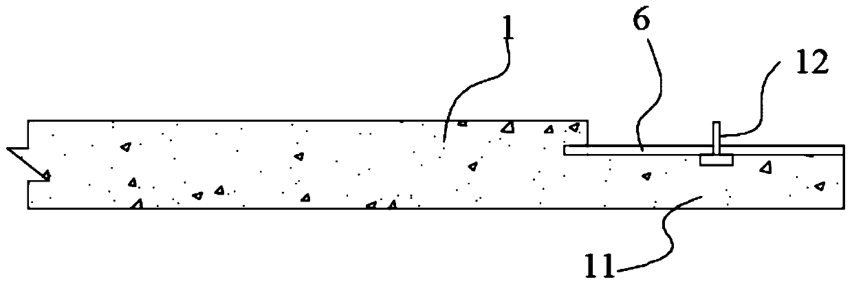
[0034] like Figure 1-6 As shown, an assembled beam slab includes a laminated beam 2 and a laminated plate 1 connected to both sides of the laminated beam 2. The middle part of the top surface of the laminated beam 2 is provided with a groove 9 along the length direction, and the groove 9 The top surfaces of the laminated beams 2 on both sides are respectively provided with pre-embedded first connecting steel plates 5, and the edges of both sides of the laminated beam 2 are provided with recesses 10 for connecting the laminated plates 1, and one end of the laminated plates 1 is provided with a The flange 11 extending in the plane direction, the second connecting steel plate 6 is embedded in the upper part of the flange 11, and the second connecting steel plate 6 extends into the interior of the main body of the laminated plate 1 by 10 mm, and the other sides are flat with the edg...


PUM


Abstract

The invention discloses a fabricated beam plate and a construction method. The fabricated beam plate comprises a laminated beam and laminated plates connected to two sides of the laminated beam. A groove is arranged in the middle of the top surface of the laminated beam, and two sides of the groove are respectively provided with a pre-embedded first connecting steel plate. The edges on the two sides of the laminated beam are provided with concave platforms for connection with the laminated plates. One end of each laminated plate is provided with a flange extending along the plane, and a secondconnecting steel plate is embedded in the upper portion of the flange. During installation, firstly the laminated beam is lifted, then the laminated plates are lifted, the flange of each laminated plate is installed in the corresponding concave platform of the laminated beam, the first connecting steel plate and the second connecting steel plate are connected through an anchoring steel plate, anda concrete layer is cast in place on the plane composed of the laminated beam and the laminated plates to form a floor slab. The anchor bolt embedding form is adopted to connect the laminated beam and the laminated plates closely. The construction is convenient, no slurry leakage or crack is generated, and the shearing resistance of connection nodes of the laminated beam and the plates is improved.

Description

technical field [0001] The invention belongs to the field of building construction, and relates to a beam-slab construction method, in particular to an assembled beam-slab and the construction method. Background technique [0002] For ordinary composite beam-slab joints, the concrete is poured after the composite slab falls on the composite beam and steel bars are laid. The working efficiency of the traditional method is low. When the concrete is poured, the steel bars are prone to deviation and grout leakage is very easy to occur, which has a great impact on the quality of the concrete forming and the structural stability of the joints. There is no technology that can well solve this problem in the prior art, which greatly affects the construction quality and construction progress. Contents of the invention [0003] The purpose of the present invention is to provide a prefabricated beam and slab and its construction method. The laminated beam and the slab are stably conn...

Claims


Application Information

Patent Timeline
Patent Type & Authority Patents(China)
IPC IPC(8): E04C3/293E04G21/00
CPCE04C3/293E04G21/00
Inventor 狄昊孙立业陈世伟张庭旺
Owner 天津一冶建设工程有限公司
Learn More