Piston horizontally opposed gear shaft output power engine
A horizontally opposed, gear shaft technology, applied in engine components, machines/engines, mechanical equipment, etc., to solve problems such as low engine energy conversion rate
- Summary
- Abstract
- Description
- Claims
- Application Information
AI Technical Summary
Problems solved by technology
Method used
Image
Examples
Embodiment 1
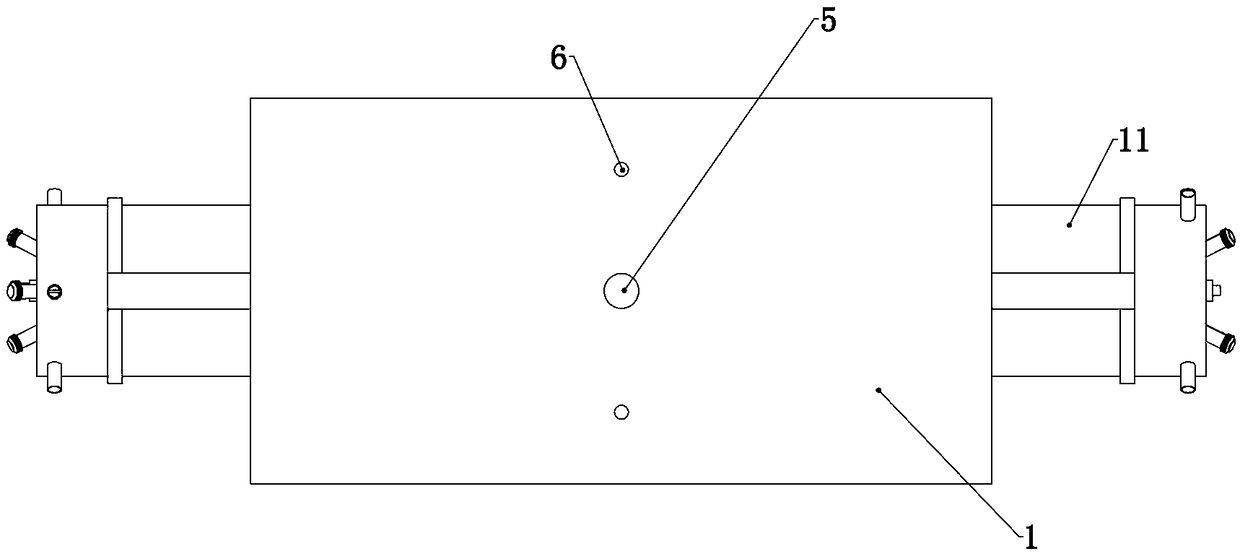
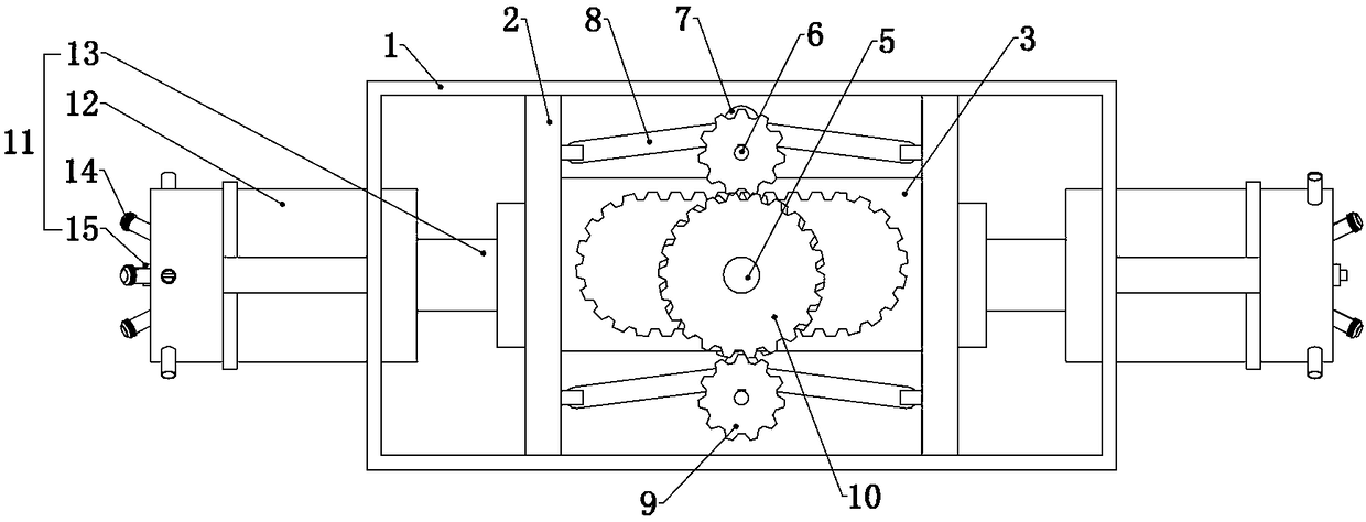
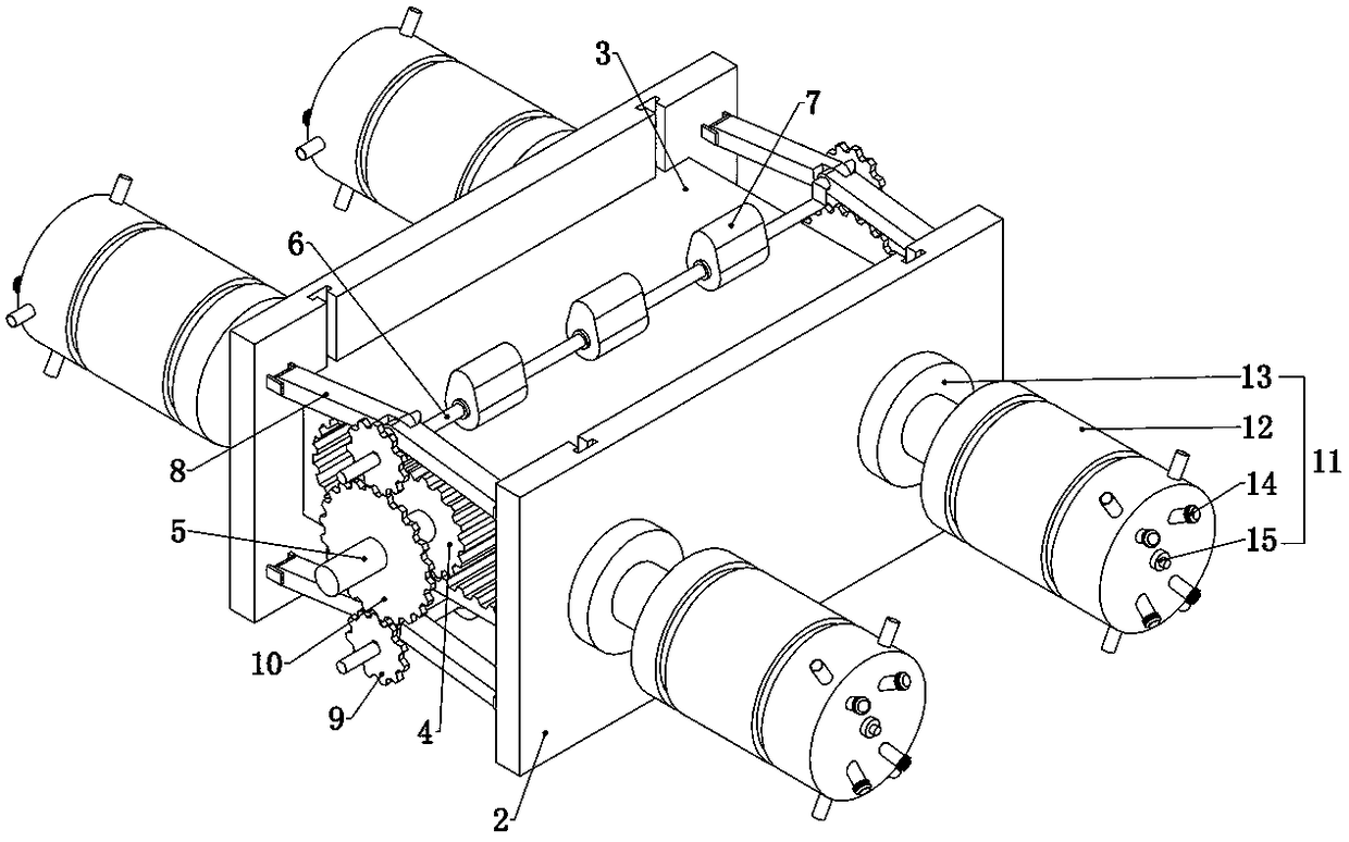
[0025] Embodiment 1, the present invention is an engine with horizontally opposed gear shafts outputting power, including a casing 1, which is similar to a common horizontally opposed engine casing, and is mainly used to provide fixation for subsequent structures The foundation is characterized in that both sides of the casing 1 are fixedly connected with a driving device with one end placed in the casing 1, and the driving device can be a cylinder of a fuel engine or other driving devices. Two push plates 2 are slidingly connected inside the casing 1, and the two push plates 2 are respectively fixedly connected with the drive device on the same side, that is, the drive device can drive the two push plates 2 slide left and right, it should be noted that the driving device located on both sides of the casing 1 should drive the corresponding push plate 2 to slide left and right, so that the two push plates 2 slide in the same direction at the same time, and the two push plates 2 ...
Embodiment 2
[0026] Embodiment 2. On the basis of Embodiment 1, this embodiment provides a specific auxiliary fixing device, so that when the driving device drives the gear frame 3 to slide to the left, it drives the gear frame 3 to slide upward, so that the gear frame 3 The output gear 4 meshes with the teeth at the lower end of the gear frame 3. When the driving device drives the gear frame 3 to slide to the right, it drives the gear frame 3 to slide downward, so that the output gear 4 and the The teeth on the upper end of the gear frame 3 are engaged, and its specific structure is that the auxiliary fixing device includes two crankshafts 6 respectively located on the upper and lower sides of the gear frame 3 and rotatably connected to the casing 1. The crankshaft 6 is fixedly connected with a plurality of cams 7, the crankshaft 6 includes a middle part, the middle part is fixedly connected with a plurality of cams 7, and both ends of the middle part are uniformly connected with cams. Th...
Embodiment 3
[0027] Embodiment 3, on the basis of Embodiment 2, this embodiment provides a structure to ensure the synchronous rotation of the crankshaft 6 located at the upper and lower ends of the gear frame 3 and ensure the stability of the present invention. Specifically, the two mentioned The crankshaft 6 is fixedly connected with a crankshaft gear 9, and the two crankshaft gears 9 are meshed with the same transmission gear 10 sleeved on the output shaft 5, that is, the two crankshafts 6 pass through the crankshaft gear 9 And the effect of transmission gear 10 has realized mutual restriction, and the setting of present embodiment does not work when two crankshafts 6 all synchronously rotate, because of the structural characteristic of crankshaft 6, when one of crankshaft 6 in two crankshafts 6 When the raised part of the raised part moves to the nearest or the farthest end from the push plate 2, it is easy to reverse, and through the restriction of the transmission gear 10 meshing with...
PUM
 Abstract
Description
Claims
Application Information
 - R&D
- Intellectual Property
- Life Sciences
- Materials
- Tech Scout
- Unparalleled Data Quality
- Higher Quality Content
- 60% Fewer Hallucinations
Browse by: Latest US Patents, China's latest patents, Technical Efficacy Thesaurus, Application Domain, Technology Topic, Popular Technical Reports.
© 2025 PatSnap. All rights reserved.Legal|Privacy policy|Modern Slavery Act Transparency Statement|Sitemap|About US| Contact US: help@patsnap.com


