Use method of plasma igniter with air channel and fuel channel

A fuel channel and air channel technology, applied in the field of plasma igniters, can solve the problems of poor ignition reliability, low ignition energy utilization rate, and small ignition energy, so as to prolong service life, improve ionization and ignition effects, and lean burn limit wide effect

Inactive Publication Date: 2019-01-25
DALIAN NATIONALITIES UNIVERSITY
View PDF4 Cites 2 Cited by
  • Summary
  • Abstract
  • Description
  • Claims
  • Application Information

AI Technical Summary

Problems solved by technology

[0005] In order to solve the problems of low ignition energy, poor ignition reliability, and low utilization rate of ignition energy when the existing heat balance plasma igniter technical scheme is applied to large-space combustion chamber (combustion space) engines (burners) and natural gas engines, The application provides a method for using a plasma igniter with an air channel and a fuel channel

Method used


Image

  • Use method of plasma igniter with air channel and fuel channel
  • Use method of plasma igniter with air channel and fuel channel
  • Use method of plasma igniter with air channel and fuel channel

Examples


Embodiment 1

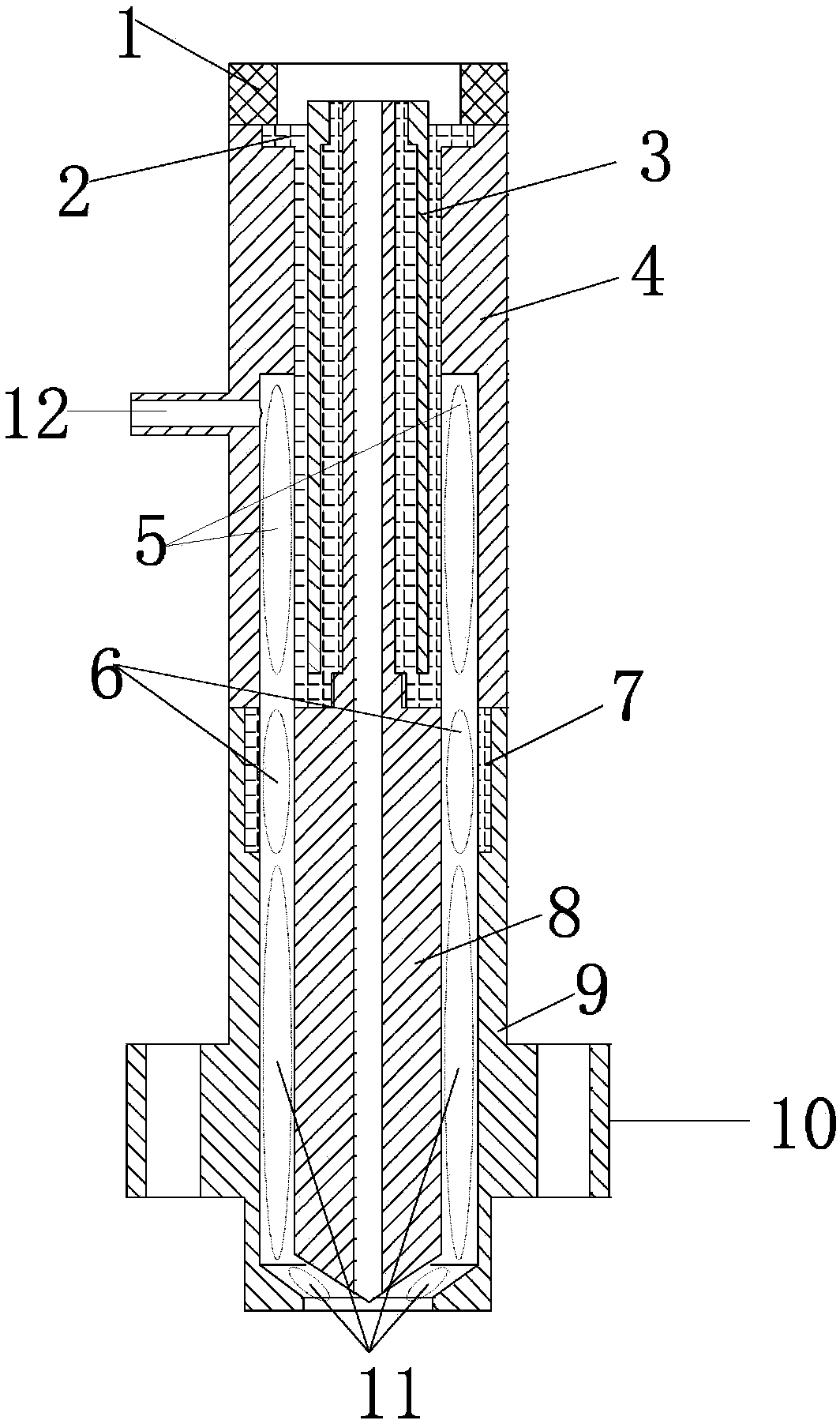
[0032] Such as figure 2 As shown, this embodiment provides a plasma igniter with a fuel channel, including an upper anode, a lower anode, an upper ground electrode, a lower ground electrode, an anode insulating sleeve, a ground electrode insulating sleeve, and fixing bolts; the upper anode is located at The central position of the igniter is installed and fixed in the anode insulating sleeve; the lower anode has a hollow structure and is installed in the installation hole in the anode insulating sleeve; the anode insulating sleeve is used to fix the upper anode and the lower anode, and realize the connection between the two insulation; the anode insulating sleeve is installed on the upper grounding electrode, and the lower end of the upper grounding electrode is connected to the lower grounding electrode; the groove between the lower grounding electrode and the upper grounding electrode is used for installing the grounding electrode insulating sleeve; the An air inlet a is pr...

Embodiment 2

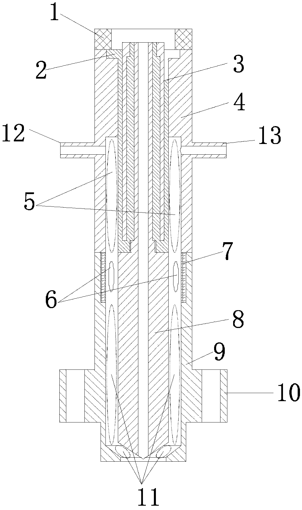
[0040] Such as image 3 As shown, this embodiment provides a plasma igniter with a fuel channel, including an upper anode, a lower anode, an upper ground electrode, a lower ground electrode, an anode insulating sleeve, a ground electrode insulating sleeve, and fixing bolts; the upper anode is located at The central position of the igniter is installed and fixed in the anode insulating sleeve; the lower anode has a hollow structure and is installed in the installation hole in the anode insulating sleeve; the anode insulating sleeve is used to fix the upper anode and the lower anode, and realize the connection between the two insulation; the anode insulating sleeve is installed on the upper grounding electrode, and the lower end of the upper grounding electrode is connected to the lower grounding electrode; the groove between the lower grounding electrode and the upper grounding electrode is used for installing the grounding electrode insulating sleeve; the There are two air inl...

Embodiment 3

[0045] Such as Figure 4 As shown, this embodiment provides a plasma igniter with a fuel channel, including an upper anode, a lower anode, an upper ground electrode, a lower ground electrode, an anode insulating sleeve, a ground electrode insulating sleeve, and fixing bolts; the upper anode is located at The central position of the igniter is installed and fixed in the anode insulating sleeve; the lower anode has a hollow structure and is installed in the installation hole in the anode insulating sleeve; the anode insulating sleeve is used to fix the upper anode and the lower anode, and realize the connection between the two insulation; the anode insulating sleeve is installed on the upper grounding electrode, and the lower end of the upper grounding electrode is connected to the lower grounding electrode; the groove between the lower grounding electrode and the upper grounding electrode is used for installing the grounding electrode insulating sleeve; the The fixing bolts are...


PUM


Abstract

The invention discloses a use method of a plasma igniter with an air channel and a fuel channel. The use method particularly includes the steps: leading in a certain quantity of air or fuels from an air inlet a in operation; supplying power for an upper anode by a power supply at low voltage, and not powering on a lower anode; performing dielectric barrier discharge among an upper grounding electrode, an anode insulating sleeve and the upper anode at low voltage, and ionizing the air or fuels positioned in an ionization space a under the action of an external electric field to generate free electrons and non-equilibrium plasma with positive charge positive ions. Owing to continuous leading-in of the air or fuels, the non-equilibrium plasma generated by ionization continues moving downwards, passes an isolation area and enters an ionization space b. The use method can combine the advantages of wide lean burn limit and high reaction activity of the non-equilibrium plasma, high working pressure of thermal equilibrium plasma and the like, and high-energy and stable ignition can be realized within a wide fuel air ratio range.

Description

technical field [0001] The invention relates to a method for using a plasma igniter, in particular to a method for using a plasma igniter with an air channel and a fuel channel. Background technique [0002] As a clean energy, natural gas has been widely used as engine fuel. In the field of vehicle power, the number of passenger cars and heavy-duty vehicles fueled by CNG is increasing; in the field of ship power, CNG and LNG-powered ships have become the key research direction in the "Made in China 2025" plan. Compared with gasoline, natural gas as a gaseous fuel requires greater ignition energy, which makes it difficult to ignite natural gas with a single spark plug even for small-bore vehicle natural gas engines in actual use, so other fuels have to be used for ignition, or setting The pre-chamber is what makes the engine work. This has led to a series of problems such as system complexity, cost increase, and reliability decrease. Therefore, it is necessary to adopt a n...

Claims


Application Information

Patent Timeline
Patent Type & Authority Applications(China)
IPC IPC(8): F02P23/04H05H1/24H05H1/48
CPCF02P23/04H05H1/2406H05H1/48
Inventor 宋鹏
Owner DALIAN NATIONALITIES UNIVERSITY
Why Eureka
Try Eureka