Actuator assembly for a transmission shifter

A technology for transmissions, actuators, applied in the direction of transmissions, elements with teeth, transmission controls, etc., which can solve the problems of loss, units cannot be located in the desired position, etc.

Inactive Publication Date: 2019-01-25
DURA OPERATING
View PDF8 Cites 4 Cited by
  • Summary
  • Abstract
  • Description
  • Claims
  • Application Information

AI Technical Summary

Problems solved by technology

If the vehicle loses power, or from the vehicle circuitry that supplies power to the shift-by-wire system, the operator's ability to control the shifting of the transmission via the shift control unit is also lost
[0003] Additionally, the space where the shift control unit is often located adjacent to the transmission and in a confined space prevents the larger unit from being located in the desired location and requires a linkage, cable or other connection

Method used


Image

  • Actuator assembly for a transmission shifter
  • Actuator assembly for a transmission shifter
  • Actuator assembly for a transmission shifter

Examples


Embodiment Construction

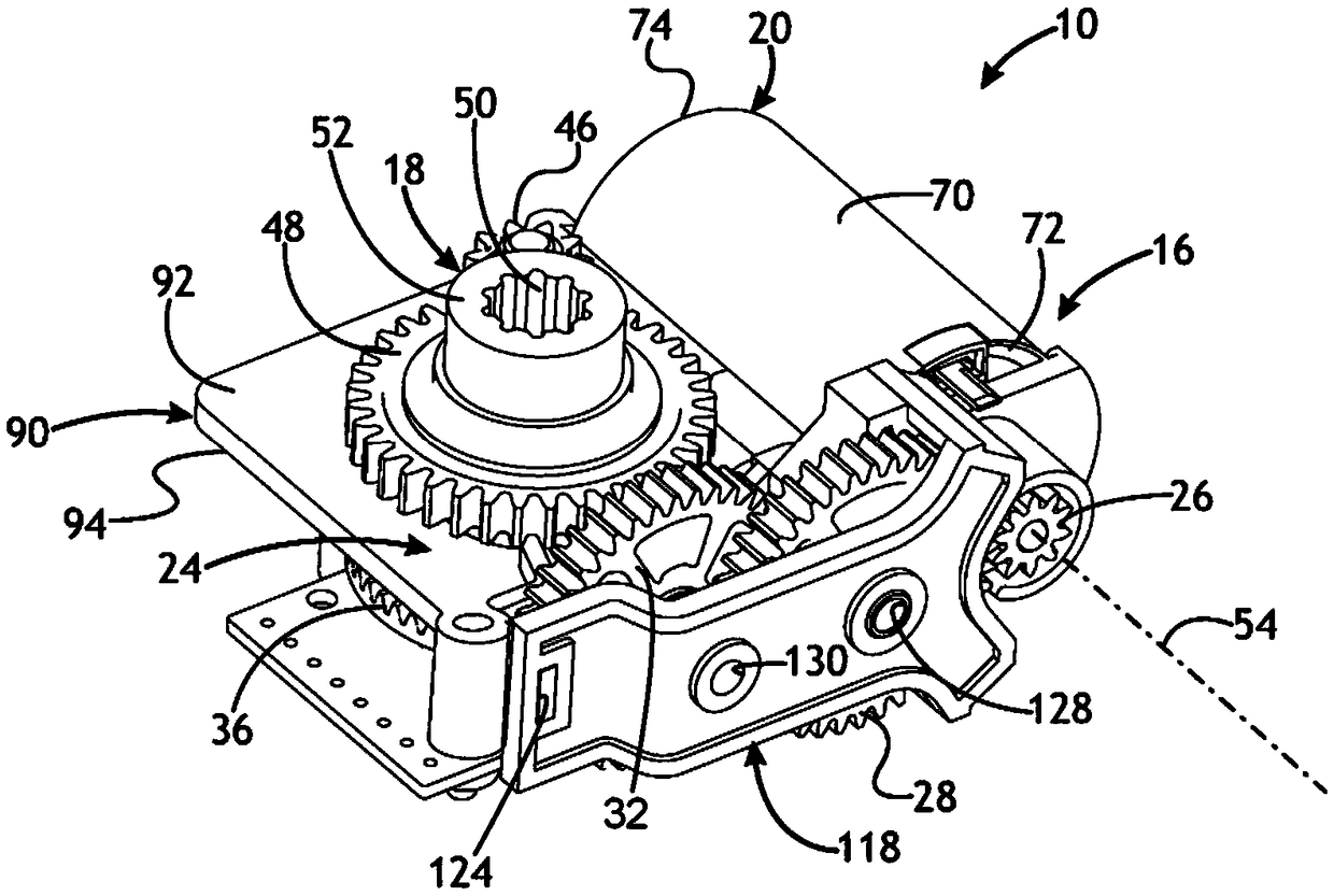
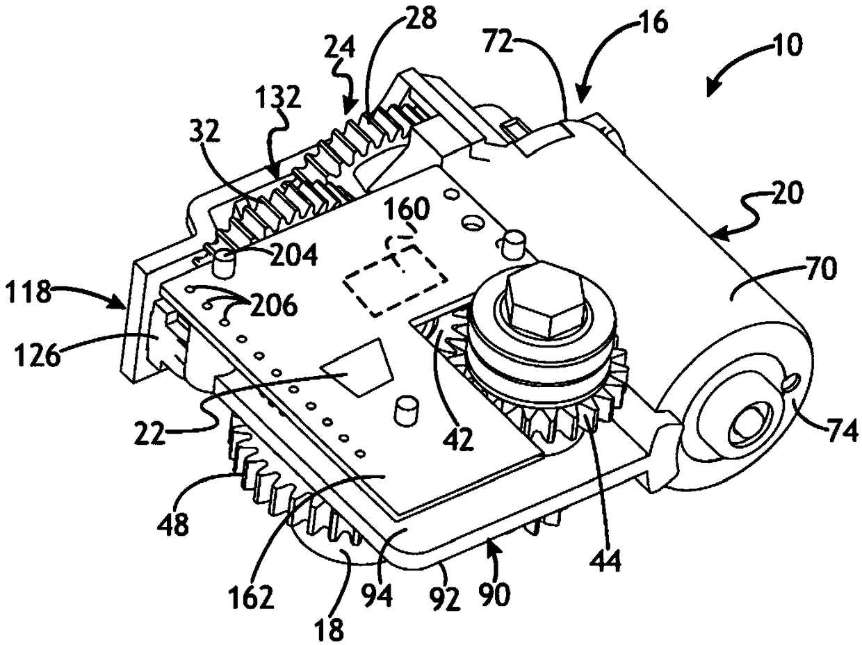
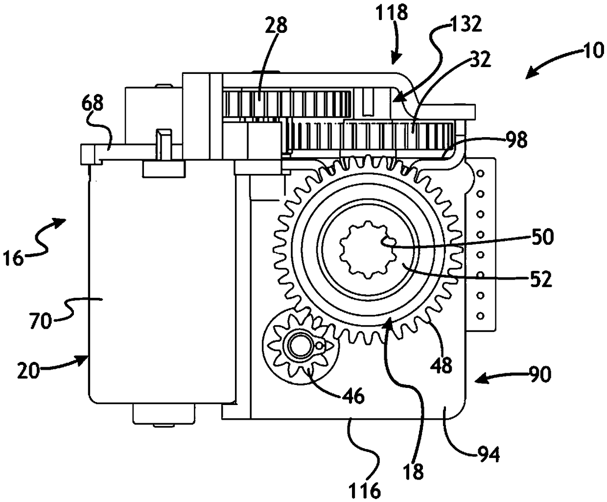
[0026] Referring to the accompanying drawings in more detail, Figure 1 to Figure 6 Shown is a shift actuator assembly 10 which is controlled by a driver-operated shift mechanism to effect shifting of the transmission, for example, shifting the transmission between Park, Neutral, Reverse, and Drive . The shift actuator assembly 10 may be part of a so-called "shift-by-wire" system in which an operator command to shift gears (for example, by turning a rotary shift knob or moving a shift lever or other shifter) is transmitted to the main drive 16 of the assembly, which is drivingly coupled to the transmission shift lever (in Figure 4 The output mechanism 18 shown schematically with 14 in the center is used to switch between the transmission gears. The actuator assembly 10 may also be used in other vehicle systems that require a rotary or linear output, such as a parking lock system, valve controller, or locking mechanism.

[0027] exist Figure 1 to Figure 6 The actuator ass...


PUM


Abstract

In at least some implementations, a gear shift actuator assembly used to cause gear changes in a vehicle transmission includes an electrically operated drive member, a drivetrain driven by the drive member, an output driven by the drivetrain for rotation to cause a gear change in the vehicle transmission and a mounting frame. The mounting frame has a drive member locating portion having at least two separate surfaces that engage an exterior of the drive member, and a drivetrain supporting portion on which the drivetrain is supported in fixed relationship relative to the drive member. The mounting frame may also include an electronics supporting portion.

Description

technical field [0001] The present invention generally relates to actuator assemblies for shift systems of vehicle transmissions. Background technique [0002] In some vehicles, an operator of the vehicle may move a gear shift lever in the vehicle's passenger compartment to shift the vehicle transmission between its park gear and other gears (eg, reverse, neutral, and drive). The shift lever is mechanically coupled to the transmission via cables that transmit movement of the shift lever to the transmission shift mechanism. Other vehicles use so-called "shift-by-wire" systems in which the operator shift lever or shift control unit is not physically coupled to the transmission shift mechanism by cables. Rather, the shift control unit is electrically coupled to a shift actuator arranged to shift the transmission upon receiving a signal from the shift control unit that an operator wants to shift the transmission gear. If the vehicle loses power, or from the vehicle circuitry t...

Claims


Application Information

Patent Timeline
Patent Type & Authority Applications(China)
IPC IPC(8): F16H59/02F16H61/32F16H63/04
CPCF16H59/02F16H61/32F16H63/04F16H2061/323F16H1/203F16H57/038F16H61/0006F16H2057/02034F16H2057/02082
Inventor J·杰恩B·D·霍韦
Owner DURA OPERATING
Why Eureka
Try Eureka