Experimental device for testing performance of microfluid inertia impact filter

An inertial impact and experimental device technology, which is applied in the direction of measuring devices, scientific instruments, suspensions and porous material analysis, etc., can solve the problems of high outlet pressure aerosol, difficult to control powder output, large powder output, etc., to achieve reduction Small experimental error, convenient disassembly and cleaning, and the effect of preventing clogging

Inactive Publication Date: 2019-01-25
NORTH CHINA ELECTRIC POWER UNIV (BAODING)
View PDF11 Cites 4 Cited by
  • Summary
  • Abstract
  • Description
  • Claims
  • Application Information

AI Technical Summary

Problems solved by technology

[0003] Due to the particularity of nuclear power, the filter must be strictly tested, but there is no published literature at home and abroad that includes an experimental device that can be used to test the filtration performance of the microfluidic inertial impact filter.
At the same time, there is no solid powder aerosol generator that can produce low-concentration, high-outlet pressure aerosols
Although the invention patent "A Double-Cylinder Multi-Stage Fluidized Circulating

Method used


Image

  • Experimental device for testing performance of microfluid inertia impact filter
  • Experimental device for testing performance of microfluid inertia impact filter
  • Experimental device for testing performance of microfluid inertia impact filter

Examples


Embodiment Construction

[0030] The embodiments will be described in detail below in conjunction with the accompanying drawings.

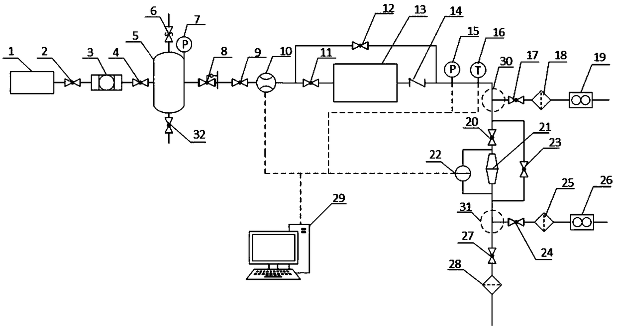
[0031] Such as figure 1 As shown, the experimental device is mainly composed of a clean air part, an aerosol distribution part, a filter part, a sampling part, a data acquisition part, and pipes and valves connecting each device. The outlet of the clean air part is connected to the inlet of the aerosol distribution part. , the outlet of the aerosol part is connected with the inlet of the filter part, the outlet of the filter part is directly connected to the atmosphere, and the inlet and outlet sampling parts are respectively connected to the inlet and outlet of the microfluid inertial impact filter.

[0032] Such as figure 1 As shown, the clean air part is mainly composed of an air compressor 1, a compressed air filter 3, and an air storage tank 5 connected in sequence. The air compressor 1 is connected with the compressed air filter 3 through the ball valve 2, the comp...


PUM


Abstract

The invention belongs to the technical field of filter equipment performance tests and especially relates to an experimental device for testing performance of a microfluid inertia impact filter. The experimental device comprises an air source, an aerosol generator, a microfluid inertia impact filter and an air filter which are sequentially connected, wherein an instrument is utilized to collect the aerosol concentration, the pressure and the temperature at an inlet/outlet of the aerosol generator and the differential pressure at an inlet/outlet of the microfluid inertia impact filter; the aerosol generator comprises an upper barrel body and a lower barrel body, the upper part and the lower part of the lower barrel body are respectively a cylinder and a reversed cone, an air flow inlet is arranged at the bottom of the reversed cone, a flow dividing pore plate is arranged at the top of the reversed cone, and a powder fluidizing plate is arranged at the top of the cylinder; an air flow outlet is arranged at the top of the upper barrel body, a vibrating motor and a powder storage pipe are respectively fixed to an outer wall of the upper barrel body, the bottom of the powder storage pipe is communicated with the middle part of an inclined feeding section and is communicated with the upper barrel body through the bottom of the inclined feeding section, and the top of the inclined feeding section is communicated with the upper part of the lower barrel body through a pipeline.

Description

technical field [0001] The invention belongs to the technical field of performance testing of filtering equipment, in particular to an experimental device for testing the performance of a microfluid inertial impact filter. Background technique [0002] Under normal circumstances, dense metal elements can almost block the penetration of all fission products. When a serious accident occurs in a nuclear power plant, the core fuel may be damaged, the fuel may melt, and interact with concrete or metal. When the molten core melts through the pressure vessel and the bottom of the containment vessel and comes into contact with concrete, a violent reaction will occur, producing a large amount of aerosols containing radioactive substances. If such aerosols are directly discharged into the atmosphere, it will seriously harm the atmospheric environment. In this case, how to filter the aerosol in the containment of the nuclear power plant in the event of an accident is very important. ...

Claims


Application Information

Patent Timeline
IPC IPC(8): G01N15/08
CPCG01N15/08G01N2015/084
Inventor 牛风雷张薇王仕集汪浩男
Owner NORTH CHINA ELECTRIC POWER UNIV (BAODING)
Why Eureka
Try Eureka