
Tensor decomposition-based multi-line TRL calibration method

A technology of tensor decomposition and calibration method, which is applied in the field of general radio frequency S parameter calibration, can solve problems such as error repetition weight, boundary jump error, and inability to accurately reflect the frequency response characteristics of the network to be tested, so as to achieve improved design requirements and avoid discontinuity Effect

Active Publication Date: 2019-01-25
临海市云谱光电有限公司
View PDF2 Cites 2 Cited by
  • Summary
  • Abstract
  • Description
  • Claims
  • Application Information

AI Technical Summary

Problems solved by technology

However, the measured S-parameter results usually obtained by vector network analyzers cannot accurately reflect the frequency response characteristics of the network under test due to the influence of non-ideal networks such as connecting lines, interfaces, adapters, and transmission lines, especially in the frequency range above GHz. parasitic and radiation effects can seriously interfere with the measurement results
In the current general-purpose multi-line TRL calibration method, each frequency response covering the entire network to be tested is formed by using multiple, redundant transmission lines as the standard network and according to the selected two-two line pairs, and through the two-two line The weight factor in the error analysis model of the pair weights the influence of each line pair to obtain the optimal propagation constant estimation and calibration parameter estimation. The selection of two line pairs will bring repeated weights of associated errors, so that in Boundary jump error on common line selection

Method used


Image

  • Tensor decomposition-based multi-line TRL calibration method
  • Tensor decomposition-based multi-line TRL calibration method
  • Tensor decomposition-based multi-line TRL calibration method

Examples


Embodiment

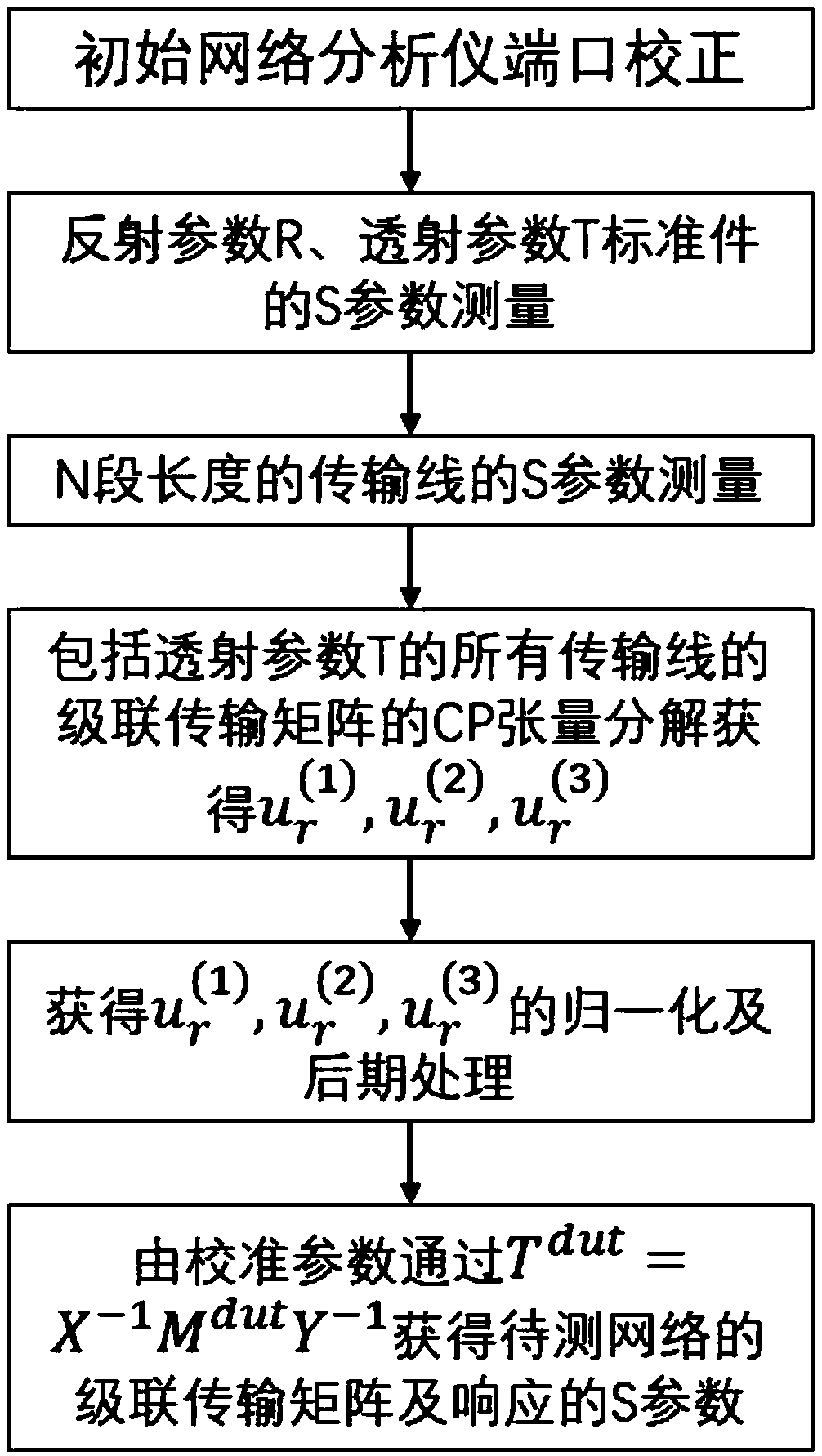
[0039] Embodiment: A kind of multi-line TRL calibration parameter calculation method based on tensor decomposition in this embodiment includes:

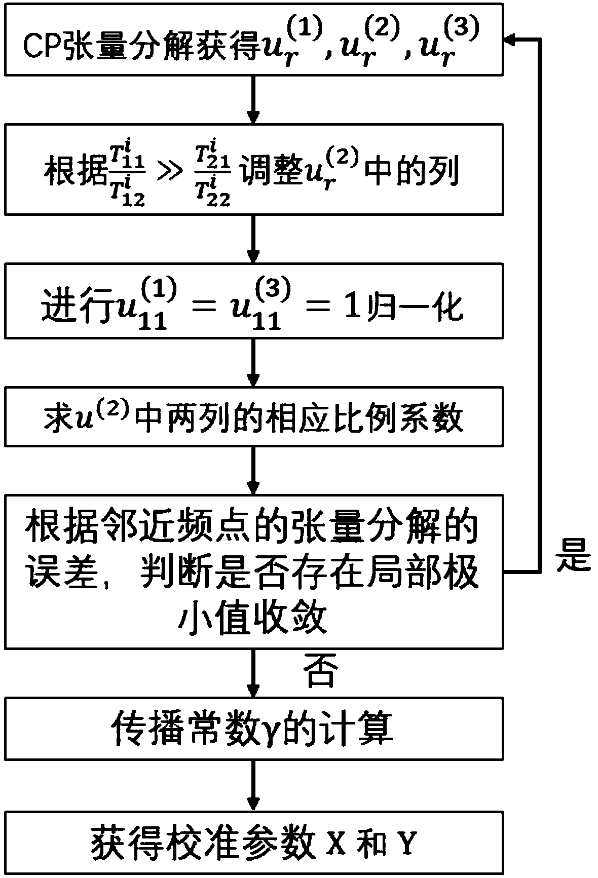
[0040] Perform synchronous CP tensor decomposition at all frequency points on the multiple and redundant N transmission lines obtained in the multi-line TRL calibration, and perform least square fitting to obtain the propagation constant by decomposing the characteristic root, and obtain it by CP tensor decomposition at the same time Required port calibration parameters.

[0041] figure 1 It is a schematic flow chart of the algorithm of the present invention.

[0042] In the preparatory steps for the CP tensor decomposition described above, include:

[0043] At any measurement frequency point, it is assumed that the length of the i-th transmission line is l i , and its two-terminal cascaded transmission matrix is ​​T i satisfy:

[0044]

[0045] And it is assumed that all transmission lines used as calibration have the same p...


PUM


Abstract

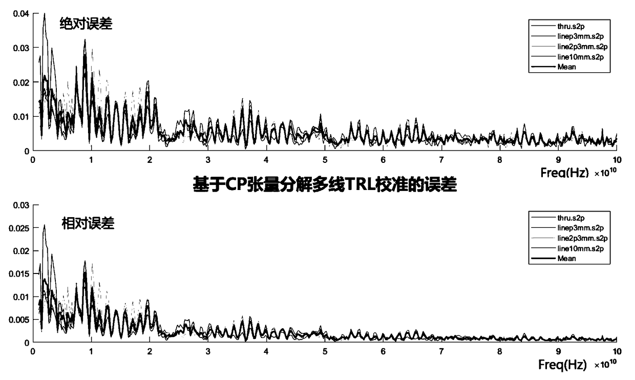
The invention discloses a tensor decomposition-based multi-line TRL calibration parameter calculation method. The method comprises the following steps that: synchronous CP tensor decomposition is performed on a plurality of redundant N transmission lines obtained in multi-line TRL calibration on all frequency points; characteristic roots obtained through decomposition are subjected to least squarefitting, so that a propagation constant is obtained; and required port calibration parameters are obtained by means of CP tensor decomposition. According to the technical schemes of the invention, the error of the classic multi-line TRL calibration can be decreased by 5 to 30 times, and therefore, the design requirements of the transmission line frequency coverage of the multi-line TRL calibration are improved. The method is suitable for the measurement calibration of an actual network analyzer or the calibration correction of simulation data.

Description

technical field [0001] The invention relates to a method for calibrating a network analyzer through a transmission line in the radio frequency field. In particular, it relates to an algorithm for universal radio frequency S-parameter calibration by decomposing the measurement results of multiple transmission lines into synchronous tensors to obtain propagation constants and calibration constants. Background technique [0002] In the field of radio frequency, S parameters reflect the frequency response characteristics of the network under test. However, due to the influence of non-ideal networks such as connecting lines, interfaces, adapters, and transmission lines, the measured S-parameter results obtained by vector network analyzers cannot accurately reflect the frequency response characteristics of the network to be tested, especially in the frequency range above GHz. The resulting parasitic and radiation effects can seriously interfere with the measurement results. In t...

Claims


Application Information

Patent Timeline
Patent Type & Authority Applications(China)
IPC IPC(8): G01R35/00G01R31/00
CPCG01R31/00G01R35/00
Inventor 白舜
Owner 临海市云谱光电有限公司
Learn More