A three-mode rectangular waveguide bandpass filter

A band-pass filter and rectangular waveguide technology, applied in the field of communication, can solve the problem of limited out-of-band suppression effect, and achieve the effects of overcoming insufficient out-of-band suppression, easy implementation, and overcoming complex structure

Inactive Publication Date: 2019-01-25
XIDIAN UNIV
View PDF6 Cites 6 Cited by
  • Summary
  • Abstract
  • Description
  • Claims
  • Application Information

AI Technical Summary

Problems solved by technology

However, this invention has limited effect on out-of-ban...

Method used


Image

  • A three-mode rectangular waveguide bandpass filter
  • A three-mode rectangular waveguide bandpass filter
  • A three-mode rectangular waveguide bandpass filter

Examples


Embodiment 1

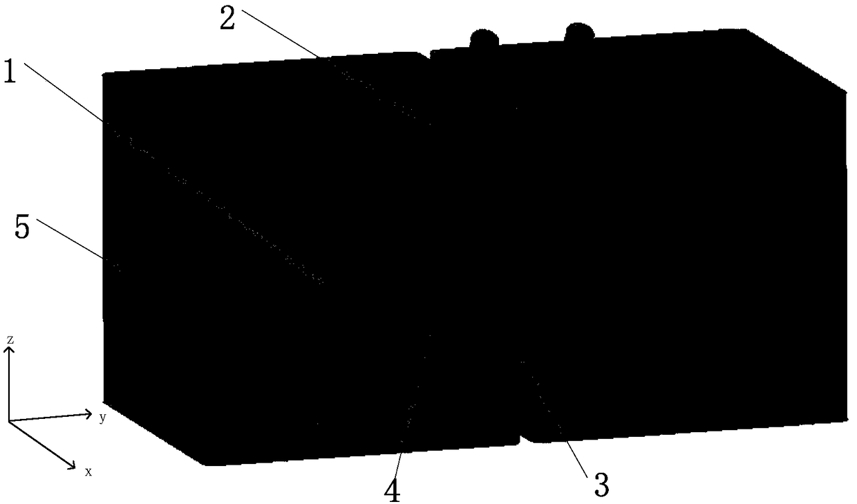
[0024] refer to figure 1 , figure 2 and image 3

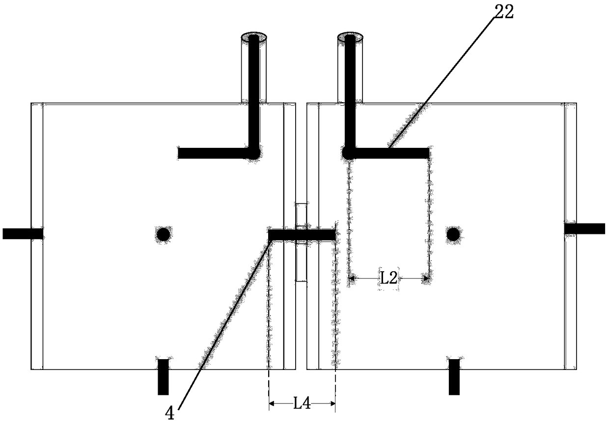
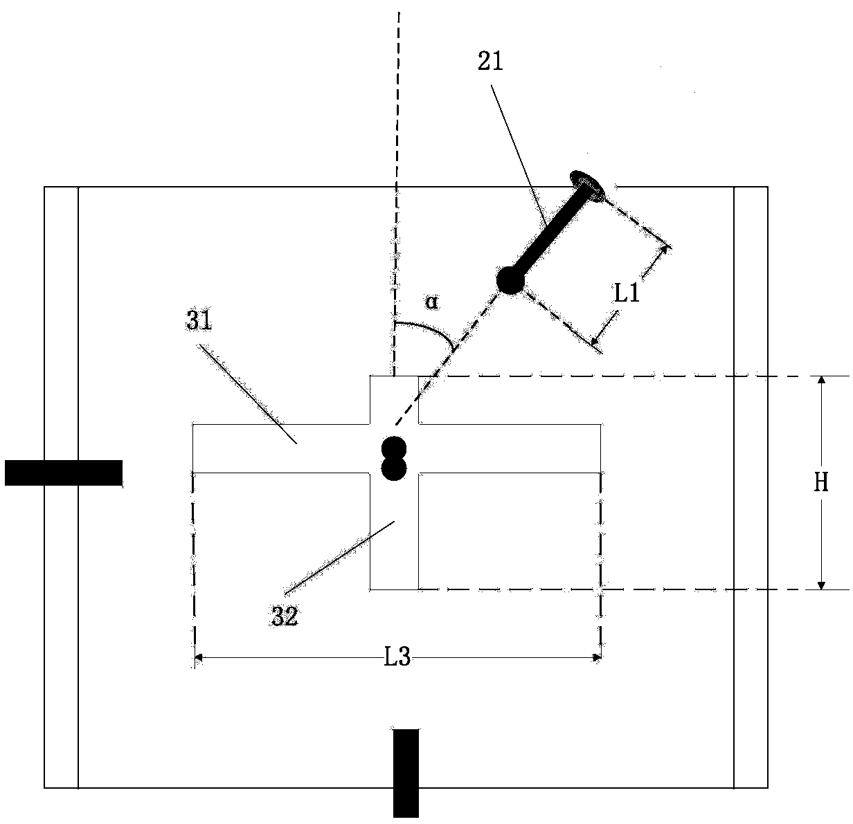
[0025] A three-mode rectangular waveguide bandpass filter, including two cubic rectangular waveguide resonators 1, the three-mode rectangular waveguide bandpass filter includes two "L"-shaped coaxial excitation 2, cross-shaped coupling window 3 with the same structure , electric probe 4 and six tuning screws 5; the "L" shaped coaxial excitation 2 is made up of a vertical excitation rod 21 and a horizontal excitation rod 22, and the end of the vertical excitation rod 21 runs through the cube On the upper surface directly above the rectangular waveguide resonator 1, the other end is fixedly connected to the horizontal excitation rod 22; the cross-shaped coupling window 3 is composed of a horizontal coupling window 31 and a vertical coupling window 32, and is fixedly arranged on two cubic rectangular Between adjacent cavity walls of the waveguide resonator 1; the electrical probe 4 passes through the cross-shaped coupling win...

Embodiment 2

[0030] The structure of this embodiment 2 is the same as that of embodiment 1, only the following parameters are adjusted:

[0031] The length L1 of the vertical excitation rod 21 extending into the cubic rectangular waveguide resonator 1=25.85mm, the angle α between the vertical excitation rod 21 and the Z axis=36.5°, the length L2 of the horizontal excitation rod 22=18mm; The length L3 of the coupling window 31 = 26.4 mm, the height H of the vertical coupling window 32 = 14.8 mm, and the length L4 of the electrical probe 4 = 8.5 mm.

Embodiment 3

[0033] The structure of this embodiment 3 is the same as that of embodiment 1, and only the following parameters are adjusted:

[0034] The length L1 of the vertical excitation rod 21 extending into the cubic rectangular waveguide resonator 1=26.85mm, the angle α between the vertical excitation rod 21 and the Z axis=37.5°, the length L2 of the horizontal excitation rod 22=19mm; The length L3 of the coupling window 31 = 27.4 mm, the height H of the vertical coupling window 32 = 15.8 mm, and the length L4 of the electrical probe 4 = 9.5 mm.

[0035] The technical effect of the present invention is further described below in conjunction with simulation result:

[0036] refer to Figure 4

[0037] 1. Simulation conditions and content:

[0038] For the described filter structure of the present invention, a simulation experiment is carried out on its performance in the 3.68GHz-3.78GHz frequency band.

[0039] Based on the commercial simulation software HFSS_15.0, the S-parameters ...


PUM


Abstract

The invention provides a three-mode rectangular waveguide bandpass filter, comprising two cubic rectangular waveguide resonators, wherein, two L-shaped coaxial excitations with the same structure, a cross-shaped coupling window, an electric probe and six tuning screws are arranged in the two cubic rectangular waveguide resonators; the cubic rectangular waveguide resonators are provided with two L-shaped coaxial excitations, a cross-shaped coupling window and six tuning screws. The L-shaped coaxial excitation consists of a vertical excitation bar and a horizontal excitation bar, the end of thevertical excitation bar penetrates the upper surface of the cubic rectangular waveguide resonant cavity, and the other end is fixedly connected with the horizontal excitation bar; The cross-shaped coupling window consists of a horizontal coupling window and a vertical coupling window, and is fixedly arranged between adjacent cavity walls of two cubic rectangular waveguide resonators. The electricprobe and the cross-shaped coupling window form a hybrid coupling structure; Three parallel topologies are formed by L shaped coaxial excitation and hybrid coupling, so that four transmission zeros are obtained and frequency selectivity is improved. The invention has simple structure and realizes miniaturization design of the filter.

Description

technical field [0001] The invention belongs to the technical field of communication, and in particular relates to a three-mode rectangular waveguide band-pass filter in radio frequency communication filtering, which can be used in radar, broadcasting, wireless communication, and measurement and control systems to select specific frequency signals. Background technique [0002] As a two-port network, the filter has specific frequency selection characteristics, that is, it allows the required frequency signal to pass smoothly while attenuating and suppressing other signals. It is currently widely used in radar, broadcasting, wireless communication, measurement and control systems and other fields. By introducing an attenuation pole at a certain frequency outside the band, that is, a transmission zero, it can bring a steep out-of-band rejection to the filter. [0003] A microwave filter is an important part of a microwave communication system, and its performance will affect t...

Claims


Application Information

Patent Timeline
IPC IPC(8): H01P1/208
CPCH01P1/2082
Inventor 吴秋逸史晓瑞张江波史小卫
Owner XIDIAN UNIV
Why Eureka
Try Eureka