Compound amorphous alloy axial flux motor

A technology of amorphous alloy and axial flux, applied in the manufacture of motor generators, synchronous motors with stationary armatures and rotating magnets, magnetic circuits, etc., can solve the limited range of field weakening and speed expansion, and the amount of permanent magnets Large, difficult to adjust the magnetic field and other problems, to achieve the effect of reducing dosage, reducing manufacturing costs, and weakening the magnetic field

Active Publication Date: 2019-01-25
SHENYANG POLYTECHNIC UNIV
View PDF10 Cites 21 Cited by
  • Summary
  • Abstract
  • Description
  • Claims
  • Application Information

AI Technical Summary

Problems solved by technology

[0003] In order to pursue the high power torque density, high efficiency and controllable effect of the magnetic field of the motor, many researchers have proposed different types of topological structures in the form of mixed excitation to solve the problem that the magnetic field of the traditional permanent magnet synchronous motor is difficult to adjust and is not conducive to the weakening of the magnetic field. and other issues, but there are still defects in varying degrees:
The feature of this invention is: by changing the current amplitude and direction in the magnetic field control winding to adjust the total magnetic flux of the air gap of the motor, so as to achieve the purpose of changing the magnitude of the induced electric potential, but the motor with this structure consumes a large amount of permanent magnets, and the speed of the weak magnetic field increases. relatively limited range

Method used


Image

  • Compound amorphous alloy axial flux motor
  • Compound amorphous alloy axial flux motor
  • Compound amorphous alloy axial flux motor

Examples


Embodiment Construction

[0038] Below in conjunction with accompanying drawing, the present invention will be further described:

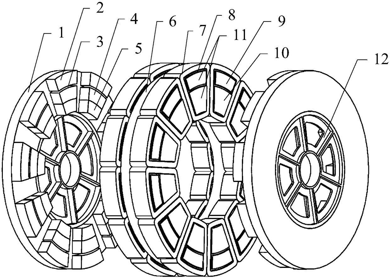
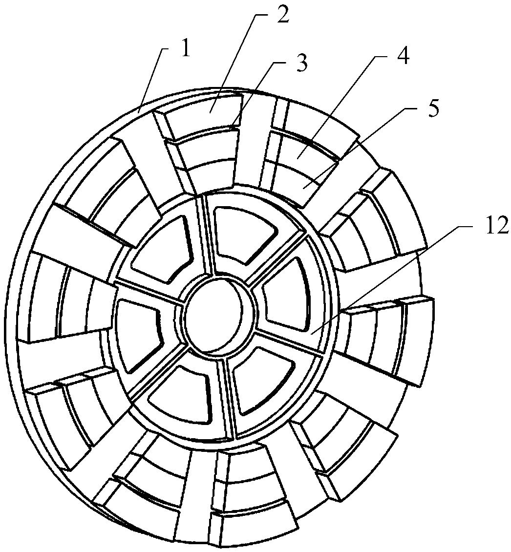
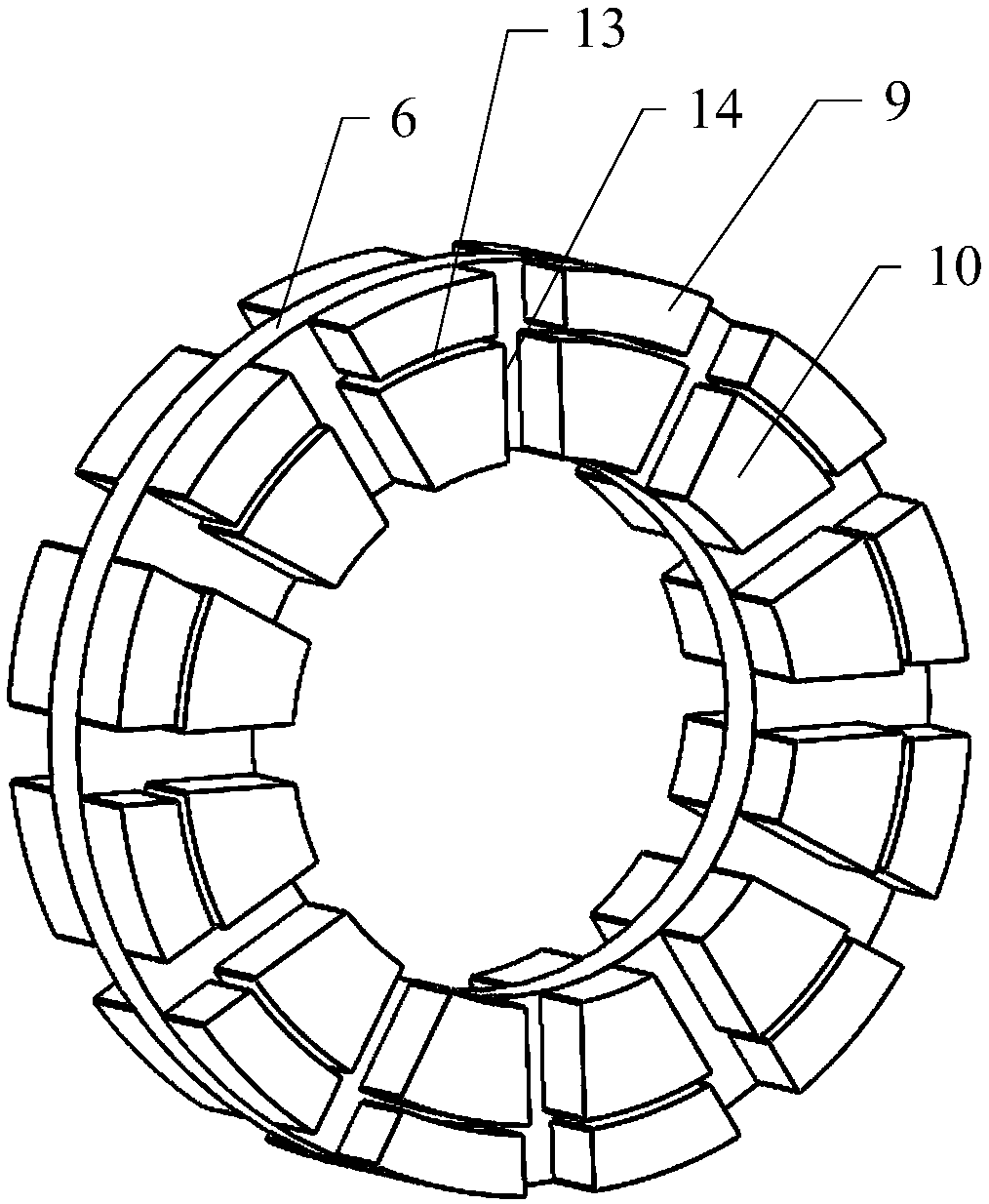
[0039] Such as figure 1 , figure 2 , image 3 , Figure 4 with Figure 5 As shown, a composite amorphous alloy axial flux motor includes a stator, a casing, an end cover, a rotating shaft, a bearing and a rotor, and is characterized in that: the stator core is an amorphous alloy stator core, and the stator core includes a stator yoke part 6 and stator tooth part 11. The stator tooth part 11 is composed of an inner tooth part 10 and an outer tooth part 9. A plurality of inner tooth parts 10 and outer tooth parts 9 are evenly distributed on the stator yoke part 6 in the circumferential direction. There is an inner tooth 10 on the inner side of each outer tooth 9, the stator core is embedded in the casing, the DC field winding 8 is wound on the outer tooth 9, and the DC field winding 8 and the outer tooth 9 are provided with The first insulator 15, each external tooth p...


PUM


Abstract

A composite amorphous alloy axial flux motor is provided. A plurality of inner tooth portions and an outer tooth portion of the stator are uniformly distributed on the stator yoke portion in the circumferential direction, the stator core is embedded in the housing, A DC excitation win is wound around that outer tooth portion, each outer tooth portion and the inner tooth portion inside of the outertooth portion are integrally wound with an armature winding, The rotor is mounted on a rotating shaft, A permanent magnet and a first soft pole are circumferentially uniformly mounted on a side of the rotor yoke close to the stator, A permanent magnet is in contact with the first soft pole, The permanent magnet and the first soft magnetic pole correspond to the circumferential position of the inner tooth part, the second soft magnetic pole corresponds to the circumferential position of the outer tooth part, the second soft magnetic pole is separated from the permanent magnet in the circumferential direction by a magnetic isolation region, end caps are respectively provided at both ends of the housing, and the rotating shaft of the motor is supported at the center of the end caps by bearings. The permanent magnet and the first soft magnetic pole correspond to the circumferential position of the inner tooth part. The invention not only inherits the characteristics of high power density,high torque density and high efficiency of the axial flux permanent magnet motor, but also has the advantages of smooth and adjustable air gap magnetic field of the electric excitation motor and thelike.

Description

technical field [0001] The invention belongs to the field of axial flux motors, and mainly relates to a composite amorphous alloy axial flux motor. Background technique [0002] Amorphous alloy strip is a new type of soft magnetic material, the strip thickness is only 0.02-0.03mm, it has excellent electromagnetic properties, good corrosion resistance, wear resistance, extremely high strength, hardness and resistivity and other characteristics. Compared with traditional silicon steel sheet, amorphous alloy has extremely small core loss, and its application as core material in motor can significantly improve the efficiency of the motor, especially for high-speed and high-frequency applications. Traditional amorphous alloy axial flux permanent magnet synchronous motors adopt a double-stator single-rotor or double-rotor single-stator structure with permanent magnet surface-mounted (or permanent magnet embedded in a non-magnetic metal disk). It has the advantages of high effici...

Claims


Application Information

Patent Timeline
Patent Type & Authority Applications(China)
IPC IPC(8): H02K21/24H02K1/14H02K1/27H02K15/02
CPCH02K1/146H02K1/2793H02K15/022H02K21/24H02K2201/03
Inventor 佟文明吴胜男王帅
Owner SHENYANG POLYTECHNIC UNIV
Why Eureka
Try Eureka