Heat dissipation device using an external air source

A technology of heat dissipation device and air source, applied in the direction of cooling/ventilation/heating transformation, etc., can solve the problems of endangering the operation of the equipment, reducing the heat dissipation performance of the heat dissipation device, and increasing the volume of the heat dissipation device, achieving high reliability, no wiring, structure and so on. simple effect

Inactive Publication Date: 2019-01-25
武汉精锋微控科技有限公司
View PDF5 Cites 0 Cited by
  • Summary
  • Abstract
  • Description
  • Claims
  • Application Information

AI Technical Summary

Problems solved by technology

The heat exchange efficiency of the forced convection heat exchange device is relatively high, but there are also the following disadvantages: 1. The forced convection heat exchange requires additional components such as fans, which makes the heat dissipation device larger and more complicated; 2. The heat dissipation fan becomes a heat dissipation device Once it fails, the heat dissipation performance of the cooling device will drop sharply, endangering the operation of the equipment; 3. The forced convection cooling device needs to open ventilation holes on the product shell to ensure air circulation. The existence of ventilation holes makes it easy for small debris to enter The interior of the electronic product leads to failure

Method used


Image

  • Heat dissipation device using an external air source
  • Heat dissipation device using an external air source
  • Heat dissipation device using an external air source

Examples


Embodiment Construction

[0022] The following will clearly and completely describe the technical solutions in the embodiments of the present invention with reference to the accompanying drawings in the embodiments of the present invention. Obviously, the described embodiments are only some, not all, embodiments of the present invention. Based on the embodiments of the present invention, all other embodiments obtained by persons of ordinary skill in the art without making creative efforts belong to the protection scope of the present invention.

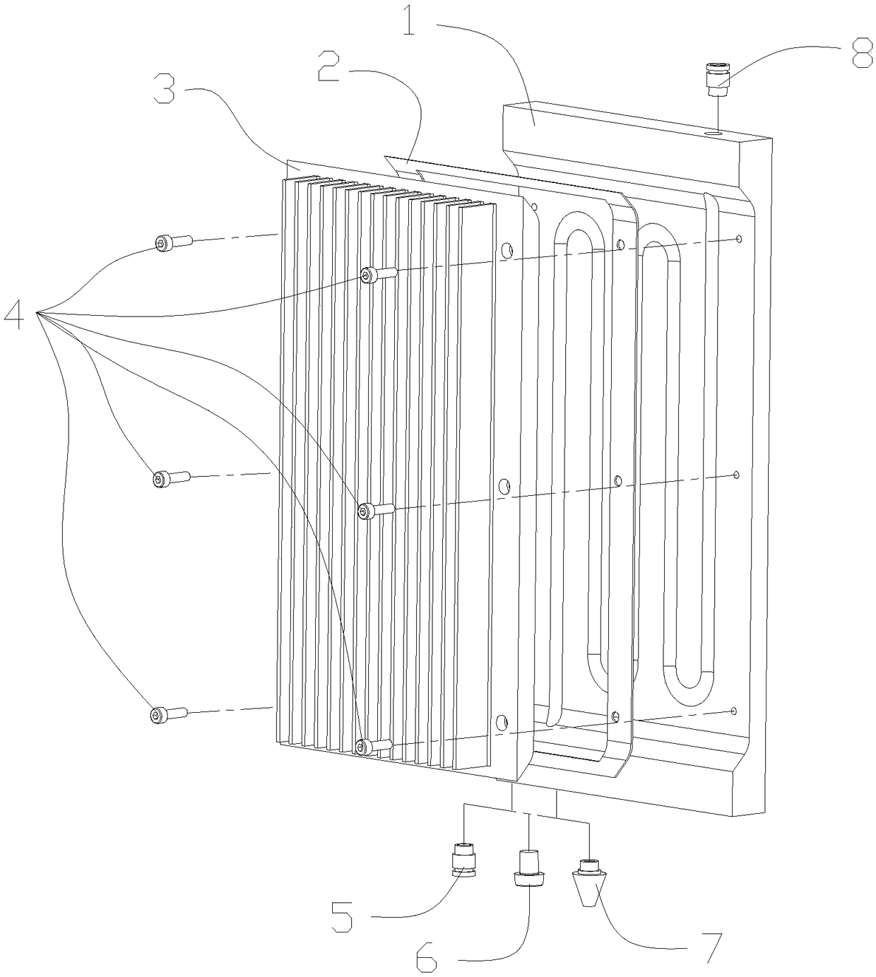
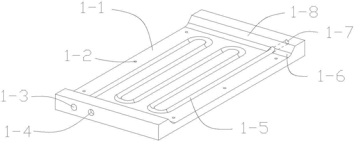
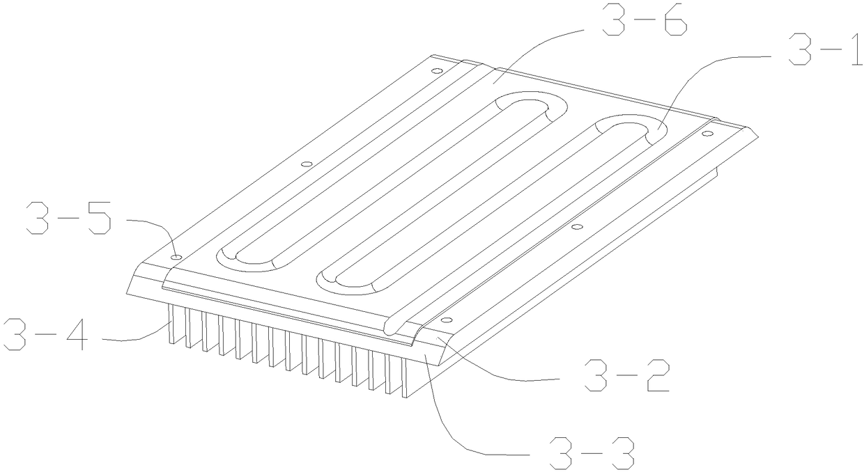
[0023] Such as figure 1 As shown, the present invention includes a heat dissipation substrate 1, a sealing gasket 2, a heat dissipation fin 3, six mounting screws 4, an air outlet joint 5, a plug 6, a muffler 7, and an air intake joint 8;

[0024] An air inlet is arranged above the heat dissipation substrate 1, and two air outlet holes are arranged below the heat dissipation substrate 1. The air inlet joint 8 is installed on the air inlet above the heat dissip...


PUM


Abstract

The invention discloses a heat dissipation device using an external air source. Include a heat dissipation substrate, sealing gasket, heat dissipation fin plat, Six mounting screws, outlet fitting, Plug, muffler, Intake connection, the heat dissipation device uses compressed air supplied from an external air source as an enhanced heat transfer medium, Introduce compressed air from the intake fitting, through the air passage between the heat dissipation substrate and the heat dissipation fin plate, the air passage is discharged from the air outlet connector or the muffler, As that compress airflows in the air passage between the heat dissipation substrate and the heat dissipation fin, heat exchange occurs with the radiator, and carrying heat out of the radiator, so as to achieve the purpose of improving the heat dissipation effect, By installing the air outlet connector, the plug and the muffler on the air outlet of the heat dissipation substrate in different combinations, the heat dissipation device can realize the switching of the natural heat dissipation mode, the normal mode and the air bypass mode, and the invention is particularly suitable for the heat dissipation of the electronic drive control system of the equipment which needs an external air source to operate.

Description

technical field [0001] The invention relates to the field of industrial control equipment, in particular to a radiator and a radiator. Background technique [0002] Electronic control drive equipment is the core of modern industrial control equipment. Any electronic control drive equipment is faced with the problem of heat generation and heat dissipation. Therefore, heat dissipation devices have become an indispensable part of electronic control drive equipment. Heat sinks can generally be divided into natural convection heat sinks and forced convection heat sinks. Natural convection heat sinks dissipate heat through convective motion caused by temperature-induced changes in gas density. The structure is relatively simple and reliable. The heat dissipation area can meet the heat dissipation requirements. With the development trend of integration and miniaturization of industrial control equipment, natural convection cooling devices have been difficult to meet the increasing...

Claims


Application Information

Patent Timeline
Patent Type & Authority Applications(China)
IPC IPC(8): H05K7/20
Inventor 胡春旭顾强
Owner 武汉精锋微控科技有限公司
Why Eureka
Try Eureka