Novel intramedullarily and extramedullarily bound bone lengthening device adopting rope wheel

A technology of internal and external integration and bone lengthening, applied in medical science, surgery, etc., can solve the problems of inability to control the length of extension, poor reliability and controllability, and prolong the treatment time of patients, so as to achieve shortened treatment time, strong applicability, compact effect

Active Publication Date: 2019-01-29
盐城日升月恒智能科技有限公司
View PDF20 Cites 0 Cited by
  • Summary
  • Abstract
  • Description
  • Claims
  • Application Information

AI Technical Summary

Problems solved by technology

However, when the device is adjusted, the extension length cannot be constantly controlled, and the extension length has great randomness. Once the extension length is too long or too short, it will increase the callus formation time, thereby prolonging the patient's treatment time. The efficiency is low and reliable. less controllable

Method used


Image

  • Novel intramedullarily and extramedullarily bound bone lengthening device adopting rope wheel
  • Novel intramedullarily and extramedullarily bound bone lengthening device adopting rope wheel
  • Novel intramedullarily and extramedullarily bound bone lengthening device adopting rope wheel

Examples


specific Embodiment approach 1

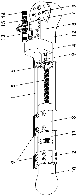
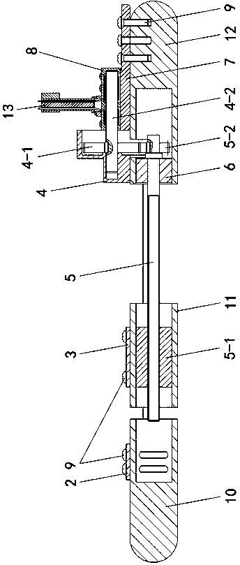
[0015] Specific implementation mode one: as Figure 1~Figure 6 As shown, the present invention discloses a novel extramedullary and extramedullary combined sheave bone extension device, which includes a fixed bone joint 2, a movable bone joint 3, a gear box 4, a lead screw 5, a fixed bone joint 2 7, and a hollow seat 8. The sheave drive frame and two guide rods 1, the two guide rods 1 are arranged side by side and fixedly installed between the fixed bone joint part 1 2 and the gear box 4, and the movable bone joint part 3 is slidably installed on the two On a guide rod 1, the screw 5 is arranged between the two guide rods 1 along the length direction, the screw 5 is screwed with an intramedullary threaded sleeve 5-1, and the intramedullary threaded sleeve 5-1 is connected with the The movable osseointegration part 3 is arranged correspondingly, the connecting end of the lead screw 5 rotates through the intramedullary shaft seat 6 and is fixedly installed with the driven gear 5...

specific Embodiment approach 2

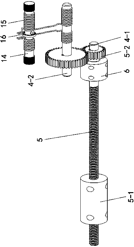
[0016] Specific implementation mode two: as figure 2 , 3 , 4, this embodiment is a further description of specific embodiment one. The sheave drive frame includes a rope drum 13, a hand-rotated rope rod 14 and two steel wire ropes 15. The bottom end of the rope drum 13 is connected to the hollow Seat 8 is fixed and connected, and the top of rope drum 13 is fixedly equipped with rope shaft seat 13-1. They are respectively fixed and tightly wound on both sides of the hand-rotating rope rod 14, and the other ends of the two steel wire ropes 15 are penetrated into the hollow seat 8 through the rope drum 13, and are respectively fixed and tightly wound on one end of the gear shaft 4-2 located in the hollow seat 8. Corresponding position, hand-rotating rope rod 14, gear shaft 4-2 and leading screw 5 diameters are identical.

specific Embodiment approach 3

[0017] Specific implementation mode three: as Figure 6 As shown, this embodiment is a further description of Embodiment 2. The two steel wire ropes 15 are respectively wound in a spring-like direction on both sides. The winding direction is the same.


PUM


Abstract

The invention provides a novel intramedullarily and extramedullarily bound bone lengthening device adopting a rope wheel, and relates to a medical instrument in orthopedics department. Two guide rodsare fixed between a fixed bone combination element 1 and a gear box; a movable bone combination element slides on the two guide rods; a lead screw is connected with an in-marrow threaded sleeve in a screwed mode; the lead screw connecting end rotationally passes through an in-marrow shaft seat and is fixed to a driven gear; a hollow seat is fixed on a fixed bone combination element 2; a rope wheeltransmission frame is fixed on the hollow seat; a gear shaft is rotationally arranged between the gear box and the hollow seat; one end, positioned in the gear box, of the gear shaft is fixedly provided with a transmission gear; the transmission gear and the driven gear are in engaged arrangement; the rope wheel transmission frame can drive one end, positioned in the hollow seat, of the gear shaft to rotate; a plurality of bone nails are arranged on each of the fixed bone combination element 1, the movable bone combination element, the gear box and the fixed bone combination element 2; the in-marrow threaded sleeve is fixed; and the in-marrow shaft seat is fixed. The bone traction lengthening can be performed all the time; the treatment time is shortened; and the pain of a patient is reduced.

Description

technical field [0001] The invention relates to an orthopedic medical device, in particular to a novel extramedullary combined sheave bone extension device. Background technique [0002] Bone lengthening is currently an effective method to treat limb shortening deformity and restore or improve limb function. Among them, callus extension of metaphysis of long tubular bone is a common osteotomy extension method with large extension length, fast bone healing, less injury, relatively few complications, and simple operation. It means that the periosteum is reserved behind the metaphyseal bone, and the mesenchymal cells in the periosteum with strong osteogenic ability will heal the bone through the formation of callus. At this time, a slow and continuous traction force is applied through the bone extension device, which can make the The callus formed at the osteotomy is slowly extended to achieve the purpose of bone lengthening. [0003] The current bone extension devices genera...

Claims


Application Information

Patent Timeline
Patent Type & Authority Applications(China)
IPC IPC(8): A61B17/56
CPCA61B17/56A61B2017/564
Inventor 周日同周求湛刘济源刘学广刘萍萍王俊
Owner 盐城日升月恒智能科技有限公司
Why Eureka
Try Eureka