Back-and-forth seaming machine, use method of back-and-forth seaming machine and air pipe production line

A reel machine, reciprocating technology, applied in the directions of forming tools, feeding devices, positioning devices, etc., can solve problems such as the influence of the accuracy of the folding shape, and achieve the effect of improving the bite efficiency, high processing efficiency, and smooth movement.

Inactive Publication Date: 2019-01-29
安徽开天重工机械制造有限公司
View PDF4 Cites 1 Cited by
  • Summary
  • Abstract
  • Description
  • Claims
  • Application Information

AI Technical Summary

Problems solved by technology

[0014] Most of the existing reeling machines can only process one side of the plate in one process, while the reeling machine that processes both sides of the plate in one process will accurately bend the edge shape of the processed plate. In order to solve the problem of seriously affecting the degree of impact, the present invention provides a reciprocating jaw bone machine, which processes the opposite sides of the plate in one process through the reciprocating motion of the jaw device, and can process both sides of the plate at one time. At the same time, it ensures the accuracy of the edge-folding shape of the plate, high processing efficiency and good edge-folding effect

Method used


Image

  • Back-and-forth seaming machine, use method of back-and-forth seaming machine and air pipe production line
  • Back-and-forth seaming machine, use method of back-and-forth seaming machine and air pipe production line
  • Back-and-forth seaming machine, use method of back-and-forth seaming machine and air pipe production line

Examples


Embodiment 1

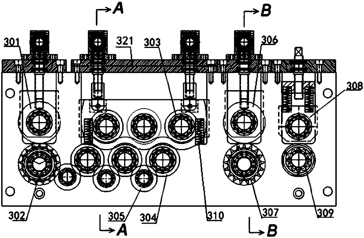
[0073] Such as image 3 As shown, this embodiment provides a leveling and beading machine, which is mainly used for leveling the tortuous sheet material, and performing beading operation on the sheet material after making the sheet material straight. Press out the longitudinal grooves. The leveling and beading machine mainly includes a pair of side plates 315 and a set of feed rollers, a set of leveling rollers, a set of beading rollers and a set of measuring rolls installed in the pair of side plates 315 in sequence. Among them, the feeding roller group is used to push the sheet material, reducing the pulling load of the sheet material in the subsequent process, making the feeding smoother; the leveling roller group is used to flatten the sheet material to make the sheet material straight; The rib roller set is used to press out the longitudinal rib groove on the sheet material, and the longitudinal rib groove will eventually become the rib groove on the side of the air duct...

Embodiment 2

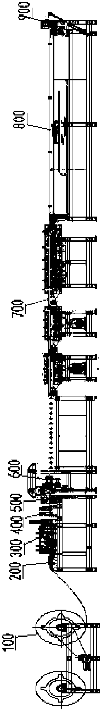
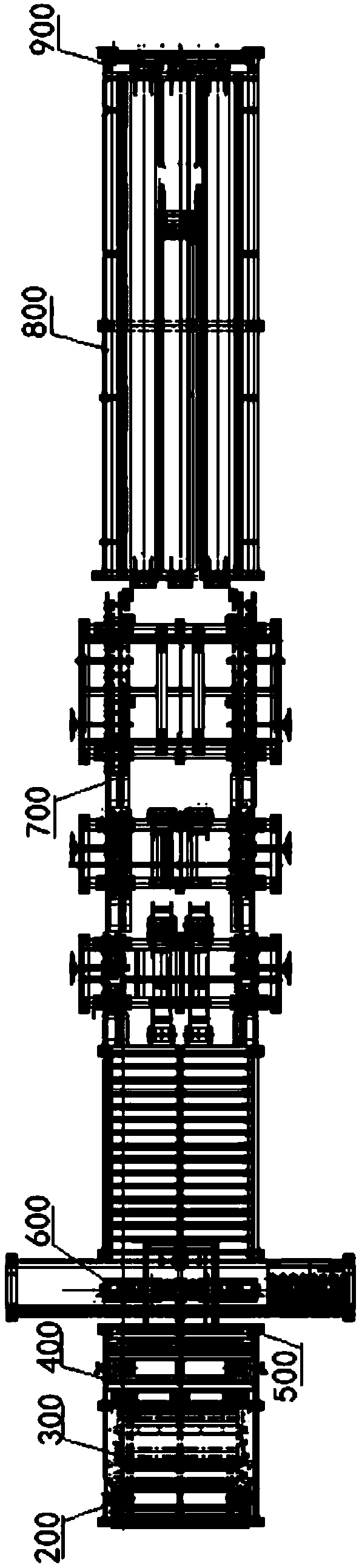
[0090] Such as Figure 1 to Figure 2 As shown, an air duct production line includes a discharging rack 100, a supporting rack 200, a leveling and beading machine 300, a stamping die 400, a shearing machine 500, a seaming riveting machine 600, and a flange machine 700 connected in sequence. , feeding device 800, bending machine 900. Wherein, the leveling and beading machine 300 adopts a leveling and beading machine in Embodiment 1.

[0091] When working, set the sheet to be processed on the material roller of the unloading rack 100 to rise and fix it tightly, let the sheet pass through the support rack 200 and then enter the leveling and beading machine 300, and enter the stamping press after the sheet is finished leveling and beading The punching hole of the mold 400 measures the length of the sheet material to be prepared by measuring rollers, and when the length of the sheet material sent out reaches a set value, the shearing machine 500 cuts the sheet material. After bein...

Embodiment 3

[0094] Such as Figure 11 As shown, this embodiment provides a reciprocating seaming machine, which is mainly used for seaming the opposite sides of the plate to form a hem, so that the plates can be spliced ​​and closed later to form an air duct, which is an air duct Indispensable equipment in production. The back-and-forth biting ruck bone machine mainly includes two major devices, namely the biting device 602 and the feeding device 603; among them, the biting device 602 moves perpendicular to the feeding direction and performs biting processing on the side of the plate, and transports the material. The device 603 is used to control the movement of the board in the feeding direction, and the two cooperate with each other to process the opposite sides of the board in one process. The structure and working principle of the bite device 602 and the material transport device 603 will be described in detail below, and the usage method of the device will be given on this basis.

...


PUM


Abstract

The invention discloses a back-and-forth seaming machine, a use method of the back-and-forth seaming machine and an air pipe production line and belongs to the field of air pipe manufacturing. The seaming machine comprises a rack, a seaming device which is installed on the rack and is capable of moving in the direction perpendicular to the feeding direction, and a material conveying device which can move in the feeding direction. The material conveying device comprises a material pressing mechanism and a material clamping mechanism. Rollers are arranged on the two sides of the moving directionof the seaming device. By means of the seaming machine, the opposite two sides of a plate are machined in one process through back-and-forth motion of the seaming device, and accuracy of the folded edge shape of the machined plate is high. By means of the use method of the back-and-forth seaming machine, the plate with the accurate folded edge shape can be obtained, the two edges of the plate aremachined in one process, and the machining efficiency is high. By means of the air pipe production line, the above back-and-forth seaming machine is adopted as the seaming machine, the air pipe machining efficiency is high, and the quality of a manufactured air pipe is good.

Description

technical field [0001] The invention belongs to the field of air duct manufacturing, and more specifically relates to a reciprocating type mouth-bracketing machine, its use method and an air duct production line. Background technique [0002] As we all know, the air duct is a piping system used for air transportation and distribution, which is widely used in various industries and is one of the indispensable components in industrial production. According to the cross-sectional shape, air ducts can be divided into circular air ducts, rectangular air ducts, oblate air ducts, etc. Among them, the circular air duct has the smallest resistance, but because the circular air duct has the largest height, the production is more complicated. Therefore, the most widely used air duct is still a rectangular air duct. [0003] Traditional air duct production mainly adopts manual methods. For example, to produce rectangular air ducts, it is necessary to manually cut the board into left si...

Claims


Application Information

Patent Timeline
Patent Type & Authority Applications(China)
IPC IPC(8): B21D19/04B21D43/09B21D37/04B21D43/00B21D43/28
CPCB21D19/043B21D37/04B21D43/003B21D43/09B21D43/287
Inventor 袁天水龚光军
Owner 安徽开天重工机械制造有限公司
Why Eureka
Try Eureka