
Steel pipe welding protection gas tool

A technology for shielding gas and steel pipes, applied in welding equipment, auxiliary welding equipment, welding/cutting auxiliary equipment, etc., can solve the problems of large amount of shielding gas, difficult welding position and difficulty, difficulty in improving welding efficiency, etc. The effect of preparation time before welding, reducing the use of shielding gas, and reducing safety hazards

Active Publication Date: 2019-01-29
CHENGXI SHIPYARD
View PDF9 Cites 0 Cited by
  • Summary
  • Abstract
  • Description
  • Claims
  • Application Information

AI Technical Summary

Problems solved by technology

[0002] In the shipbuilding process, a large number of steel pipes are involved in the welding construction. The welding volume of steel pipes is large, and the welding position and difficulty are large, so it is difficult to improve the welding efficiency. At the same time, the welding process of steel pipes needs to be flushed with shielding gas throughout the process, and the amount of shielding gas used is large. It puts pressure on production costs, and a large amount of protective gas diffuses on the construction site, which poses certain safety hazards

Method used


Image

  • Steel pipe welding protection gas tool
  • Steel pipe welding protection gas tool
  • Steel pipe welding protection gas tool

Examples


Embodiment 1

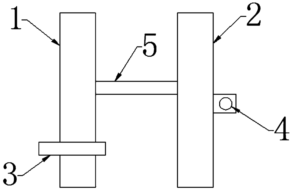
[0019] Such as figure 1 As shown, a steel pipe argon arc welding inflatable tooling of the present invention includes a left seal 1 and a right seal 2, the left seal and the right seal are closely matched with the inner wall of the steel pipe, and the left seal is provided with a through hole Argon inflating tube 3 is arranged in the through hole, and the opposite side of the left seal and / or the right seal is provided with a hanging ring 4 for fixing the traction part, and the hanging ring is connected with the traction outside the steel pipe. file connection. The opposite surfaces of the left seal and the right seal are connected by a limit rod 5, so that the distance between the left seal and the right seal is 10-20cm.

[0020] The limit rod can be a straight rod, and two blind holes are arranged on the relative positions of the left seal and the right seal. The distance between them should be avoided if the distance is too small, there is not enough argon to protect the ...

Embodiment 2

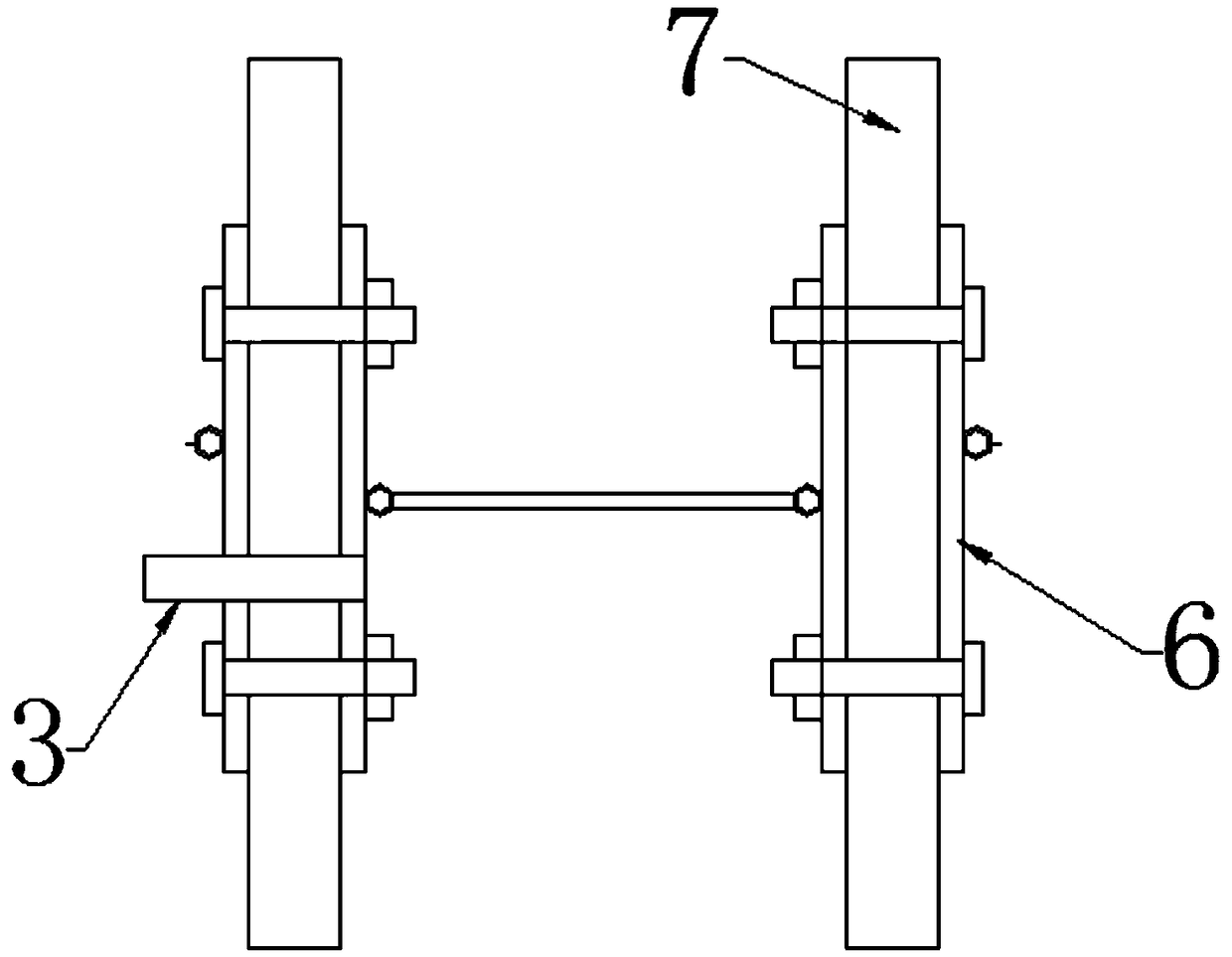
[0022] Such as figure 2 As shown, the difference between Embodiment 2 and Embodiment 1 is that the seal is composed of a splint 6 and a seal ring made of flexible material, the outer diameter of the splint 6 is smaller than the inner diameter of the steel pipe, and a seal ring is sandwiched between the splints. The inflation tube runs through the splint. The sealing ring is a circular sheet sponge 7 with a thickness of 5-10 cm. The splint is fixed with the sponge sealing ring through the cooperation of bolts and nuts.

Embodiment 3

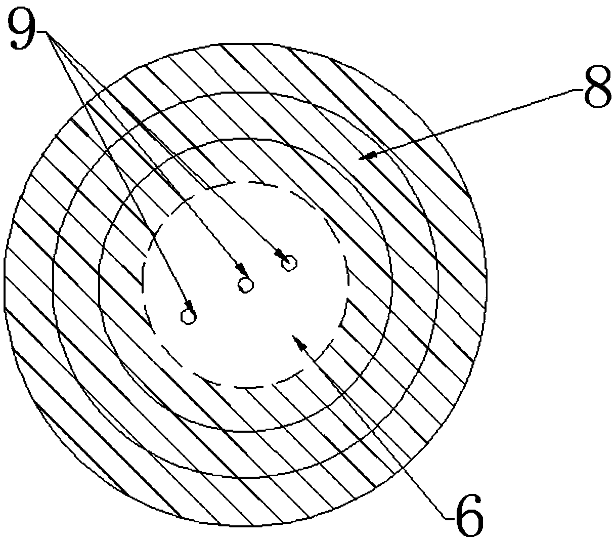
[0024] Such as image 3 As shown, the difference between embodiment 3 and embodiment 2 is that the sealing ring is an air bag 8 sandwiched in the splint 6, and the inflation port 9 of the air bag is arranged on the plane of the splint. The airbag is a three-layer annular airbag, wherein each layer of annular airbag has a separate inflation port.


PUM

PropertyMeasurementUnit
thicknessaaaaaaaaaa

Abstract

The invention discloses a steel pipe welding protection gas tool comprising a left sealing member and a right sealing member. The left sealing member and the right sealing member are in tight fit withthe inner wall of a steel pipe, at least one sealing member is provided with a through hole, an air inflation tube is arranged in the through hole, fixing portions for fixing traction members are arranged on the opposite sides of the left sealing member and / or the right sealing member, and the fixing portions are connected with the traction members arranged outside the steel pipe. The tool has the advantages of being simple in structure and convenient to use, reducing the using quantity of protective gas, and reducing the production cost. Compared with the manner than a whole pipe is filled with the protection gas, the using quantity of the protective gas can be saved by more than half, and the air inflation quality is guaranteed; the air inflation time is shortened, the welder efficiencyis improved, and the preparation time before welding is shortened; and use of the protective gas is reduced, the air inflation efficiency is improved, safety hazards are reduced, and the quality of welding is ensured.

Description

technical field [0001] The invention relates to the technical field of welding tooling, in particular to a protective gas tooling for steel pipe welding. Background technique [0002] In the shipbuilding process, a large number of steel pipes are involved in the welding construction. The welding volume of steel pipes is large, and the welding position and difficulty are large, so it is difficult to improve the welding efficiency. At the same time, the welding process of steel pipes needs to be flushed with shielding gas throughout the process, and the amount of shielding gas used is large. It puts pressure on production costs, and a large amount of protective gas diffuses on the construction site, which poses certain safety hazards. Therefore, how to reduce the use of shielding gas and ensure the welding quality of steel pipes during the on-site welding process is an urgent problem to be solved in the current on-site construction. Contents of the invention [0003] The ob...

Claims


Application Information

Patent Timeline
Patent Type & Authority Applications(China)
IPC IPC(8): B23K37/00B23K101/06B23K103/04
CPCB23K37/00
Inventor 王亚
Owner CHENGXI SHIPYARD
Learn More