
Environment-friendly fermentation device for new energy biogas

A fermentation device and new energy technology, applied in the field of environmental protection fermentation devices for new energy biogas, can solve the problems that the temperature of the fermentation device cannot be adjusted, cannot meet the needs of use, and the biogas residue is inconvenient to discharge, and achieves good isolation effect and high practicability. , The effect of preventing splashing

Inactive Publication Date: 2019-01-29
肖江江
View PDF0 Cites 2 Cited by
  • Summary
  • Abstract
  • Description
  • Claims
  • Application Information

AI Technical Summary

Problems solved by technology

[0003] The biogas fermentation system is based on the principle of biogas fermentation, with the goal of energy production, and finally realizes the comprehensive utilization of biogas, biogas slurry, and biogas residue. Biogas is a mixed gas produced by the fermentation of microorganisms under anaerobic conditions. Biogas fermentation needs to be carried out in a fermentation device. The existing biogas fermentation device has a simple design and structure, the temperature in the fermentation device cannot be adjusted, and the fermentation efficiency is low. Moreover, the biogas residue in the fermentation device is inconvenient to discharge, which obviously cannot meet people's needs. Usage requirements

Method used

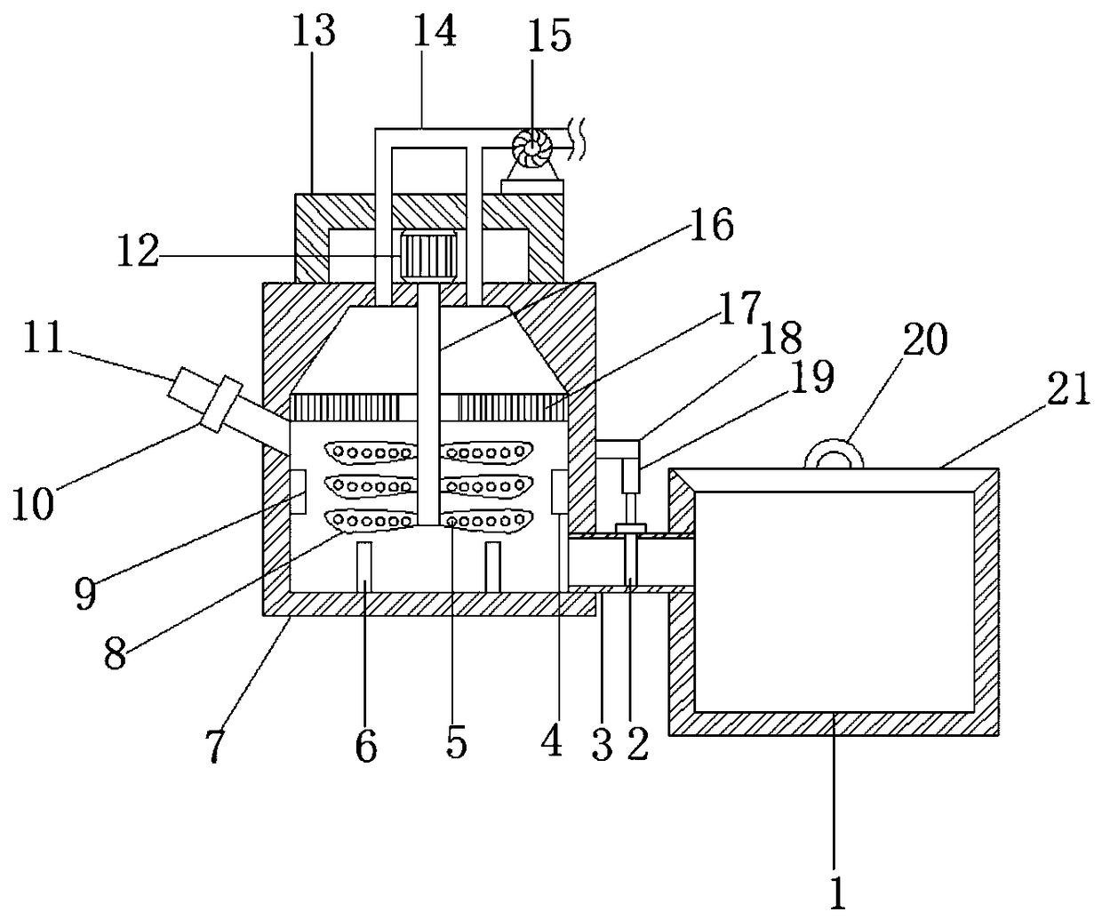
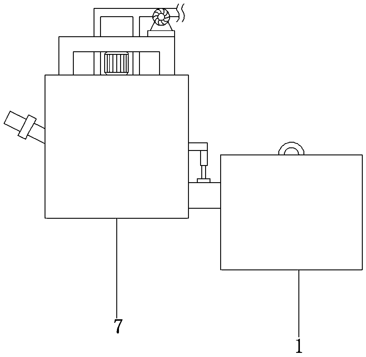
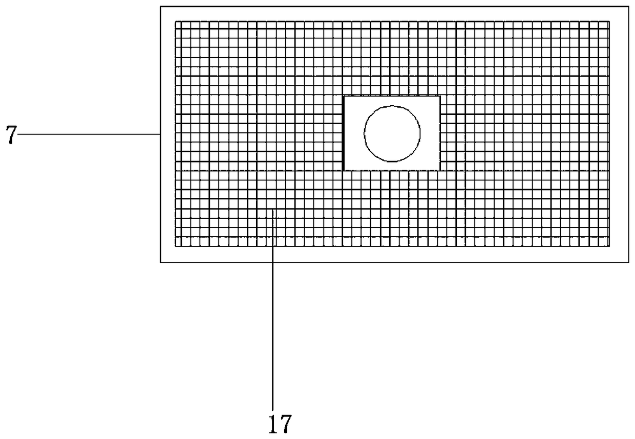

Image

  • Environment-friendly fermentation device for new energy biogas
  • Environment-friendly fermentation device for new energy biogas
  • Environment-friendly fermentation device for new energy biogas

Examples


Embodiment Construction

[0021] The following will clearly and completely describe the technical solutions in the embodiments of the present invention with reference to the accompanying drawings in the embodiments of the present invention. Obviously, the described embodiments are only some, not all, embodiments of the present invention.

[0022] In describing the present invention, it should be understood that the terms "upper", "lower", "front", "rear", "left", "right", "top", "bottom", "inner", " The orientation or positional relationship indicated by "outside", etc. is based on the orientation or positional relationship shown in the drawings, and is only for the convenience of describing the present invention and simplifying the description, rather than indicating or implying that the referred device or element must have a specific orientation, so as to Specific orientation configurations and operations, therefore, are not to be construed as limitations on the invention.

[0023] refer to Figure ...


PUM


Abstract

The invention discloses an environment-friendly fermentation device for new energy biogas. The environment-friendly fermentation device comprises a fermentation tank and a biogas residue pool, an electric motor is fixed to the outer wall of the top of the fermentation tank through bolts, an output shaft of the electric motor is connected with a rotating rod through a coupling, stirring blades arewelded to the outer wall of the rotating rod, and through holes are formed in the outer walls of the stirring blades; a supporting table is fixed to the position, at the outer wall of the top of the upper part of the electric motor, of the fermentation tank through bolts, and an air pump is fixed to the outer wall of the top of the supporting table through bolts; an air outlet pipe sleeves the input end of the air pump, and the end, away from the air pump, of the air outlet pipe communicates with the fermentation tank; a horizontally arranged installation plate is fixed to the outer wall of one side of the fermentation tank through bolts, and a hydraulic cylinder is fixed to the outer wall of the bottom of the installation plate through bolts. According to the environment-friendly fermentation device for the new energy biogas, the fermentation efficiency of the biogas is significantly improved, the fermentation amount of the biogas is increased, practicability is high, biogas residue is automatically discharged, and the use needs of people are met.

Description

technical field [0001] The invention relates to the technical field of fermentation devices, in particular to an environment-friendly fermentation device for new energy biogas. Background technique [0002] Biogas fermentation, also known as anaerobic digestion and anaerobic fermentation, refers to the process in which organic substances are catabolized by various microorganisms under certain moisture, temperature and anaerobic conditions, and finally form flammable mixed gases such as methane and carbon dioxide. [0003] The biogas fermentation system is based on the principle of biogas fermentation, with the goal of energy production, and finally realizes the comprehensive utilization of biogas, biogas slurry, and biogas residue. Biogas is a mixed gas produced by the fermentation of microorganisms under anaerobic conditions. Biogas fermentation needs to be carried out in a fermentation device. The existing biogas fermentation device has a simple design and structure, the t...

Claims


Application Information

Patent Timeline
Patent Type & Authority Applications(China)
IPC IPC(8): C12M1/38C12M1/36C12M1/34C12M1/107C12M1/02
CPCC12M21/04C12M27/02C12M41/24C12M41/44
Inventor 肖江江李南姜瑶
Owner 肖江江
Learn More