In-situ nondestructive concrete carbonization depth measurement device and method thereof

A carbonization depth and measuring device technology, which is applied to measuring devices, suspension and porous material analysis, instruments, etc., can solve the problems of insufficient representativeness of detection results and large errors of manual observation, so as to facilitate subsequent calculation and processing and avoid cleaning work , easy to clean effect

Inactive Publication Date: 2019-01-29
ZHEJIANG INST OF HYDRAULICS & ESTUARY
View PDF6 Cites 4 Cited by
  • Summary
  • Abstract
  • Description
  • Claims
  • Application Information

AI Technical Summary

Problems solved by technology

[0007] The purpose of the present invention is to solve the problems of insufficient representativeness of detection results of traditional concrete carbonation depth detection methods and large manual observation errors, thereby providing a concrete carbonation depth that does not need to measure the carbonation depth of all points to be measured and has a small error In-situ non-destructive measurement device and method

Method used


Image

  • In-situ nondestructive concrete carbonization depth measurement device and method thereof
  • In-situ nondestructive concrete carbonization depth measurement device and method thereof
  • In-situ nondestructive concrete carbonization depth measurement device and method thereof

Examples


Embodiment 1

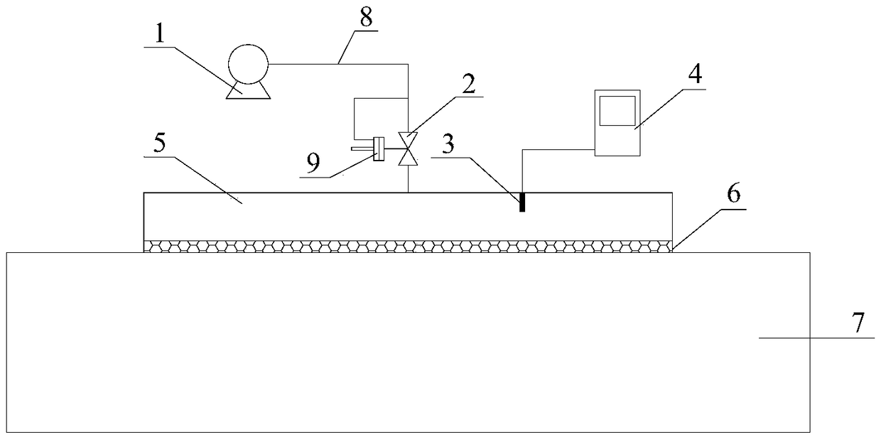
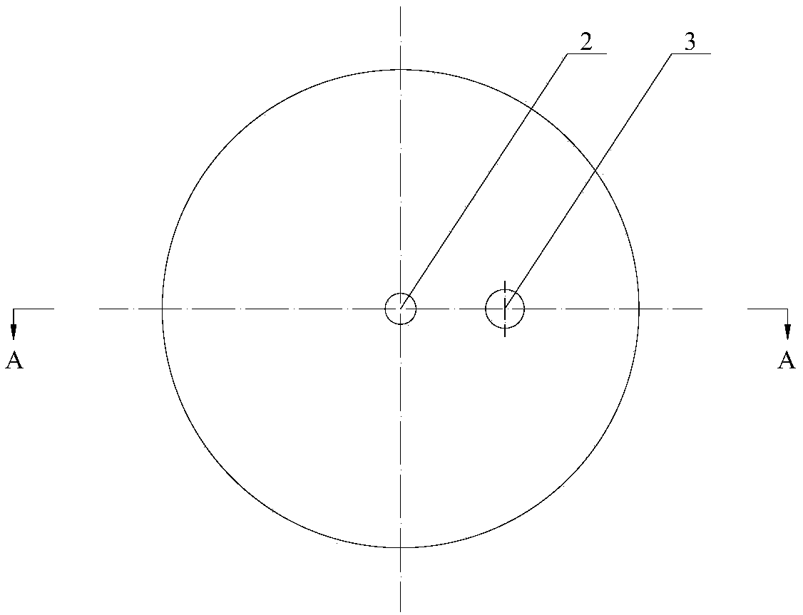
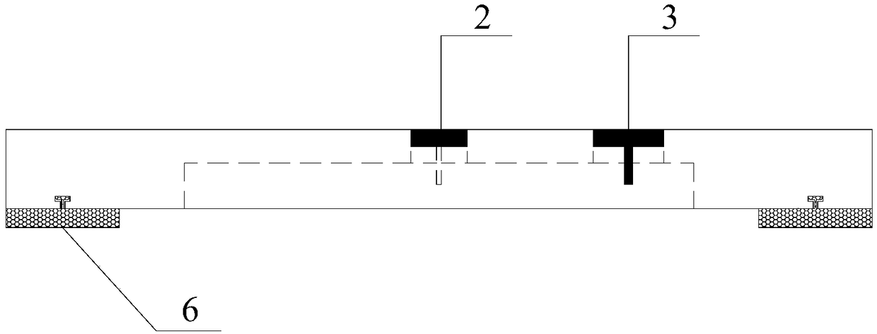
[0047] Attached below Figure 1-3 , the present invention will be further described.

[0048] An in-situ non-destructive measurement device for the carbonation depth of concrete, comprising an air compressor 1, an air valve 2, a pressure sensor 3, a data acquisition system 4, a measuring head 5, a rubber bottom ring 6 and a pressure regulating valve 9, and a The rubber bottom ring 6, the probe 5 includes the probe cavity and the probe air inlet, one end of the pressure sensor 3 is connected to the probe cavity, the other end of the pressure sensor 3 is connected to the data acquisition system 4, and the probe air inlet passes through the air pipe 8 It is connected with the air valve 2, the air valve 2 is connected with the air compressor 1 through the air pipe 8, the air compressor 1 is connected with the pressure regulating valve 9 through the air pipe 8, and the pressure regulating valve 9 is connected with the air valve 2. The measuring head 5 and the rubber bottom ring 6 ...

Embodiment 2

[0074] The rest are the same as in Embodiment 1 except that a thin layer of rubber sealing ring is provided on the bottom surface of the rubber bottom ring 6 of the present invention, and the thin layer of rubber sealing ring and the rubber bottom ring 6 are connected in a detachable manner (such as by bonding).

[0075] Simultaneously in the step (2) of the present invention, the lower part of the measuring head 5 is connected with a rubber bottom ring 6 by snap-fitting, and a thin-layer rubber sealing ring is installed on the bottom of the rubber bottom ring 6 in a detachable manner, and the lower surface of the thin-layer rubber sealing ring is the same as The surface of the concrete member 7 to be tested is in close contact. Choose a thin-layer rubber sealing ring that can be bonded on both sides. The upper surface is bonded to the bottom of the rubber bottom ring 6, and the lower surface is bonded to the surface of the concrete component 7 to be tested. The thin-layer rubb...


PUM


Abstract

The invention relates to the field of concrete structure durability of civil and hydraulic engineering, in particular to an in-situ nondestructive concrete carbonization depth measurement device and amethod thereof. The in-situ nondestructive concrete carbonization depth measurement device comprises an air compressor, an air valve, a pressure sensor, a data acquisition system, a measuring head, arubber bottom ring, and a pressure regulating valve. The rubber bottom ring is arranged below the measuring head; the measuring head comprises a measuring head cavity and a measuring head air inlet;one end of the pressure sensor is connected to the measuring head cavity, and the other end of the pressure sensor is connected to the data acquisition system; the measuring head air inlet is connected to the air valve through an air pipe; the air valve is connected to the air compressor through the air pipe; the air compressor is connected to the pressure regulating valve through the air pipe; and the pressure regulating valve is connected to the air valve. According to the in-situ nondestructive concrete carbonization depth measurement device and the method thereof, from the perspective of region, the carbonization depth of certain part of the concrete can be quantitatively described based on the mapping relation between air permeability and the carbonization depth of the concrete; and compared with a traditional carbonization depth point measurement mode, the adverse effect to the measurement result brought by human factors is reduced.

Description

technical field [0001] The invention relates to the field of durability of concrete structures in civil and hydraulic engineering, in particular to an in-situ non-destructive measurement device and method for carbonation depth of concrete. Background technique [0002] Carbonation of concrete refers to the CO in the air 2 It reacts with the liquid-phase alkaline substances in the concrete, which makes the alkalinity of the concrete decrease and the chemical composition of the concrete change the neutralization reaction process. Since concrete is a porous medium, CO in the atmosphere 2 In the case of suitable humidity, it can decompose and react with the hydration products in cement to generate CaCO 3 . [0003] The pore water of concrete is calcium hydroxide saturated liquid, and its pH value is about 12-13, which is strongly alkaline. Due to carbonization, calcium hydroxide turns into calcium carbonate, the original strong alkalinity of cement stone gradually decreases,...

Claims


Application Information

Patent Timeline
Patent Type & Authority Applications(China)
IPC IPC(8): G01B21/18G01N15/08
CPCG01B21/18G01N15/0826
Inventor 谢中凯陈文亮章晓桦王良苏玉杰曹敏富海文那彬彬高海峰
Owner ZHEJIANG INST OF HYDRAULICS & ESTUARY
Why Eureka
Try Eureka