
Method for Measuring the Effective Diffusion Coefficient of Radon in Thin Films

A technology of diffusion coefficient and thin film, applied in the field of nuclear radiation detection, can solve problems such as long time

Active Publication Date: 2021-04-20
HENGYANG NORMAL UNIV
View PDF6 Cites 0 Cited by
  • Summary
  • Abstract
  • Description
  • Claims
  • Application Information

AI Technical Summary

Problems solved by technology

The existing measurement method only measures the effective diffusion coefficient of radon in the film through a film, and the measurement process takes a long time

Method used


Image

  • Method for Measuring the Effective Diffusion Coefficient of Radon in Thin Films
  • Method for Measuring the Effective Diffusion Coefficient of Radon in Thin Films
  • Method for Measuring the Effective Diffusion Coefficient of Radon in Thin Films

Examples


Embodiment 1

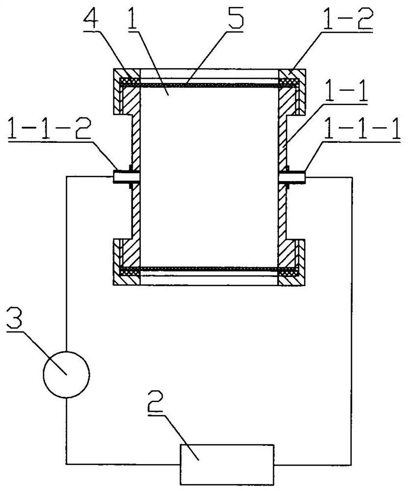
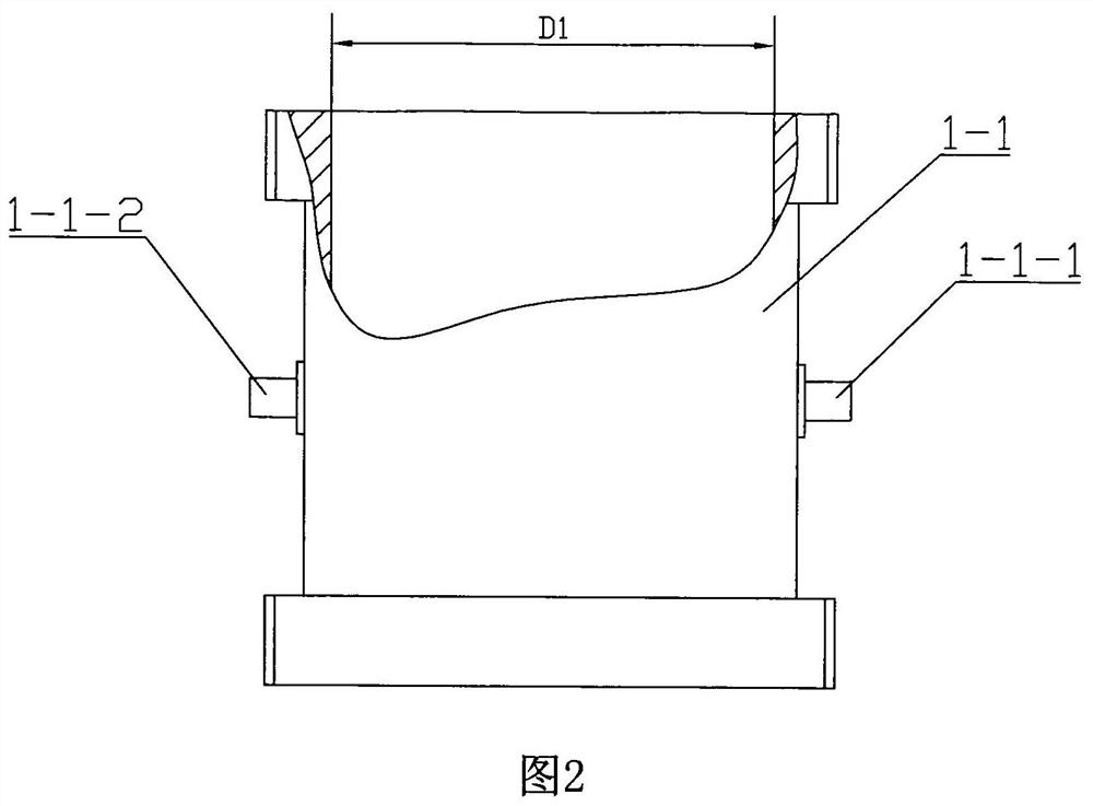
[0060] Embodiment 1. A device for measuring the effective diffusion coefficient of radon in a thin film, including a measuring chamber 1 , a radon measuring instrument 2 , a pump 3 and an annular sealing gasket 4 .

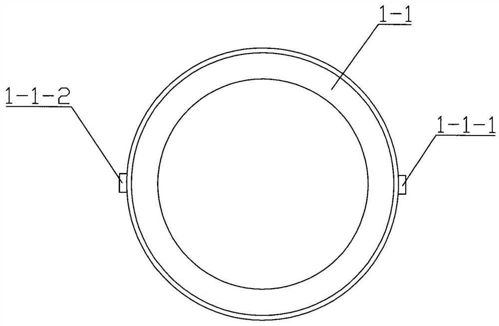
[0061] The measuring chamber 1 includes a threaded cylindrical cylinder 1-1 at both ends and threaded end caps 1-2 connected to the two ends of the cylindrical cylinder 1-1, on the wall of the cylindrical cylinder 1-1 The air outlet joint 1-1-1 and the air intake joint 1-1-2 are symmetrically arranged, the inner diameter of the cylindrical cylinder 1-1 is D1, and the threaded end cap 1-2 is provided with an annular groove 1-2- 1. An annular sealing gasket 4 is installed in the annular groove 1-2-1, and the hole diameter on the end cover plate of the threaded end cover 1-2 is D2, where D1=D2.

[0062] The gas outlet joint 1-1-1 on the measurement chamber 1 is connected to the gas inlet of the radon meter 2 through a pipeline, the gas outlet of the radon meter 2 is ...

Embodiment 2

[0088] Embodiment 2, compared with Embodiment 1, the difference is: on the cylinder wall of the cylindrical cylinder 1-1, four cylindrical measuring chambers 6 are added, and the cylindrical measuring chamber 6 is connected with the cylindrical cylinder 1-1. The inner cavity of 1 is connected, and the inner diameter of the cylindrical measuring cavity 6 is the same as that of the cylindrical barrel 1-1. The structure of the end of the cylinder body 1-1 is the same as that of the threaded end cap 1-2 connected with the cylindrical cylinder body 1-1.

[0089] The method of measuring the effective diffusion coefficient of radon in the film by using the above-mentioned measuring device through six films is as follows, which includes the measurement process and the calculation process:

[0090] 1. Measurement process:

[0091] A. Cut the film to be measured into a circular film sheet 5 with the same diameter as the outer diameter of the port of the cylindrical cylinder 1-1, and at...


PUM


Abstract

A device and method for measuring the effective diffusion coefficient of radon in a thin film. The measuring device includes a measuring chamber, a radon measuring instrument, a pump and an annular sealing gasket. The measuring chamber consists of a cylindrical cylinder and threaded end caps connected to both ends of the cylindrical cylinder. The cylinder wall of the cylindrical cylinder is provided with a gas outlet joint and an air inlet joint. An annular sealing gasket, the gas outlet connector on the measurement chamber is connected to the inlet port of the radon meter, the gas outlet port of the radon meter is connected to the inlet port of the pump, and the gas outlet port of the pump is connected to the inlet connector of the measurement chamber. The measurement method includes the measurement process and the calculation process. During the measurement, the film material to be measured is cut into a circular film sheet with the same diameter as the outer diameter of the cylindrical cylinder port, respectively attached to the two ends of the cylindrical cylinder, and threaded end caps are used. Compress and seal, put the cylindrical measuring chamber into the standard radon chamber, measure the variation trend of the radon concentration in the cylindrical cylinder, and obtain the effective diffusion coefficient of radon in the thin film by calculation after measurement.

Description

technical field [0001] The invention relates to the technical field of nuclear radiation detection, in particular to a device and method for measuring the effective diffusion coefficient of radon in a thin film. Background technique [0002] Radon is a radioactive inert gas harmful to the human body. Radon in the air environment mainly comes from the precipitation on the surface of the medium. Due to mine radiation protection and indoor radon pollution, it is necessary to use a dense film to prevent radon from entering the working and living environment. The effective diffusion coefficient of radon in the film can be used to evaluate the barrier performance of the film to radon. The existing method for measuring the effective diffusion coefficient of radon in the film is generally to use a film to divide the inner cavity of the measurement chamber into two measurement chambers, wherein One measurement cavity injects high concentration radon, and the high concentration radon...

Claims


Application Information

Patent Timeline
Patent Type & Authority Patents(China)
IPC IPC(8): G01N13/00G01T1/167
CPCG01N13/00G01N2013/003G01T1/167
Inventor 袁红志谭延亮
Owner HENGYANG NORMAL UNIV
Learn More