Novel wheel electroplating spraying equipment

A technology of spraying equipment and wheels, which is applied in the direction of spraying booths, spraying devices, etc., can solve the problems of high labor intensity, short service life, and heavy workload of workers, so as to reduce labor intensity and workload, reduce overall production costs, and improve The effect of production efficiency

Inactive Publication Date: 2019-02-01
赵斌
View PDF0 Cites 3 Cited by
  • Summary
  • Abstract
  • Description
  • Claims
  • Application Information

AI Technical Summary

Problems solved by technology

[0002] Car hubs are easily scratched by stones or infested by insect harmful substances, causing the hubs to rust easily. Therefore, many car manufacturers will protect the hubs accordingly to prolong the service life of the hubs. Currently, the wheel hub protection technology is widely used The scheme includes electroplating and spray painting. The two technical schemes have their own advantages and disadvantages. In the low-end automobile industry, only one of the protective measures is often used for protection. However, this technical method of protection often suffers from unavoidable defects This leads to some problems in use, such as short service life, high maintenance cost, easy to be infringed, poor resistance, and difficult to repair again. Due to the inevitable defects of individual protection, the high-end market gradually tends to multiple protection, that is, simultaneous Electroplating protection and painting protection, but currently there is no corresponding production line that can carry out double protection treatment at the same time. In the existing technical scheme, only one technical assembly line can be split into two assembly lines for separate operation. This approach can realize technical Requirements, but there are long process flow time, complex process flow, low production efficiency, and the labor intensity of workers is high, the workload is also high, and the overall production cost is high.

Method used


Image

  • Novel wheel electroplating spraying equipment

Examples


Embodiment

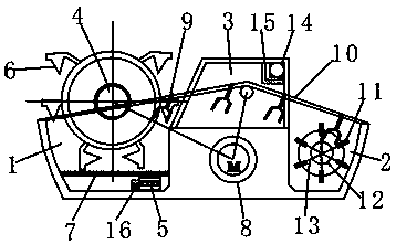
[0015] see figure 1 , the present invention provides a technical solution: a new type of wheel electroplating and spraying equipment, including an electroplating pool 1 and a painting booth 2, the electroplating pool 1 and the painting booth 2 are connected by a drying channel 3, and the top of the electroplating pool 1 A swivel frame 4 is installed, and the electroplating pool 1 includes a metal box 5 to be plated, a clip 6 to be plated and a barrier net 7, and the metal box 5 to be plated and the clip 6 to be plated are respectively arranged on both sides of the barrier net 7, and the metal box to be plated 5 is arranged below the barrier net 7, and the clamps 6 to be plated are arranged above the barrier net 7, and the number of the clamps 6 to be plated is six, and the six clamps 6 to be plated are mutually fixed at 60° and rotated. On the frame 4, the rotary frame 4 is driven by a motor 8, and an unloading frame 9 is provided on the rotation direction of the rotary frame ...


PUM


Abstract

The invention discloses novel wheel electroplating spraying equipment. The equipment comprises an electroplating pool and a painting chamber; the electroplating pool and the painting chamber are connected through a drying channel; a rotating frame is mounted at the top of the electroplating pool; the electroplating pool comprises a plating layer metal box, a clip to be plated, and a barrier net; the plating layer metal box and the clip to be plated are arranged on two sides of the barrier net; the rotating frame is driven through a motor; an unloading frame is arranged in the rotating direction of the rotating frame, and is connected with the motor through a conveying belt; the conveying belt is arranged in the drying channel; the painting chamber comprises a painting head, a paint storagebox and a conducting pipe; the painting head is connected with the paint storage box through the conducting pipe; an air blower is mounted in the drying channel; and a high-heat heating wire is mounted in an air outlet of the air blower. The equipment can perform the electroplating and painting treatment on a production line, reduces the labor intensity and the workload, simplifies the process flow, improves the production efficiency, and reduces the comprehensive production cost.

Description

technical field [0001] The invention relates to the technical field of automobile equipment, in particular to a novel wheel electroplating and spraying equipment. Background technique [0002] Car hubs are easily scratched by stones or infested by insect harmful substances, causing the hubs to rust easily. Therefore, many car manufacturers will protect the hubs accordingly to prolong the service life of the hubs. Currently, the wheel hub protection technology is widely used The scheme includes electroplating and spray painting. The two technical schemes have their own advantages and disadvantages. In the low-end automobile industry, only one of the protective measures is often used for protection. However, this technical method of protection often suffers from unavoidable defects This leads to some problems in use, such as short service life, high maintenance cost, easy to be infringed, poor resistance, and difficult to repair again. Due to the inevitable defects of individu...

Claims


Application Information

Patent Timeline
Patent Type & Authority Applications(China)
IPC IPC(8): B05B16/20B05B13/02
CPCB05B16/20B05B13/0221
Inventor 赵斌
Owner 赵斌
Why Eureka
Try Eureka