Oil immersion machine

An oil immersion machine and oil immersion technology, which is applied in the direction of pretreatment surface, coating, and surface coating liquid device, etc., can solve the problems of low work efficiency, time-consuming and labor-intensive, etc., and achieve fast oil immersion speed and use The effect of long life and reasonable structure

Inactive Publication Date: 2019-02-01
苏州司达夫超声科技有限公司
View PDF8 Cites 4 Cited by
  • Summary
  • Abstract
  • Description
  • Claims
  • Application Information

AI Technical Summary

Problems solved by technology

[0003] In the traditional process, the oil immersion and blowing are processed by two separate machines. After the oil immersion treatment is completed, it needs to enter the next machine for blowing treatment. In this way, the work efficiency is low, time-consuming and labor-intensive.

Method used


Image

  • Oil immersion machine
  • Oil immersion machine

Examples


Embodiment 1

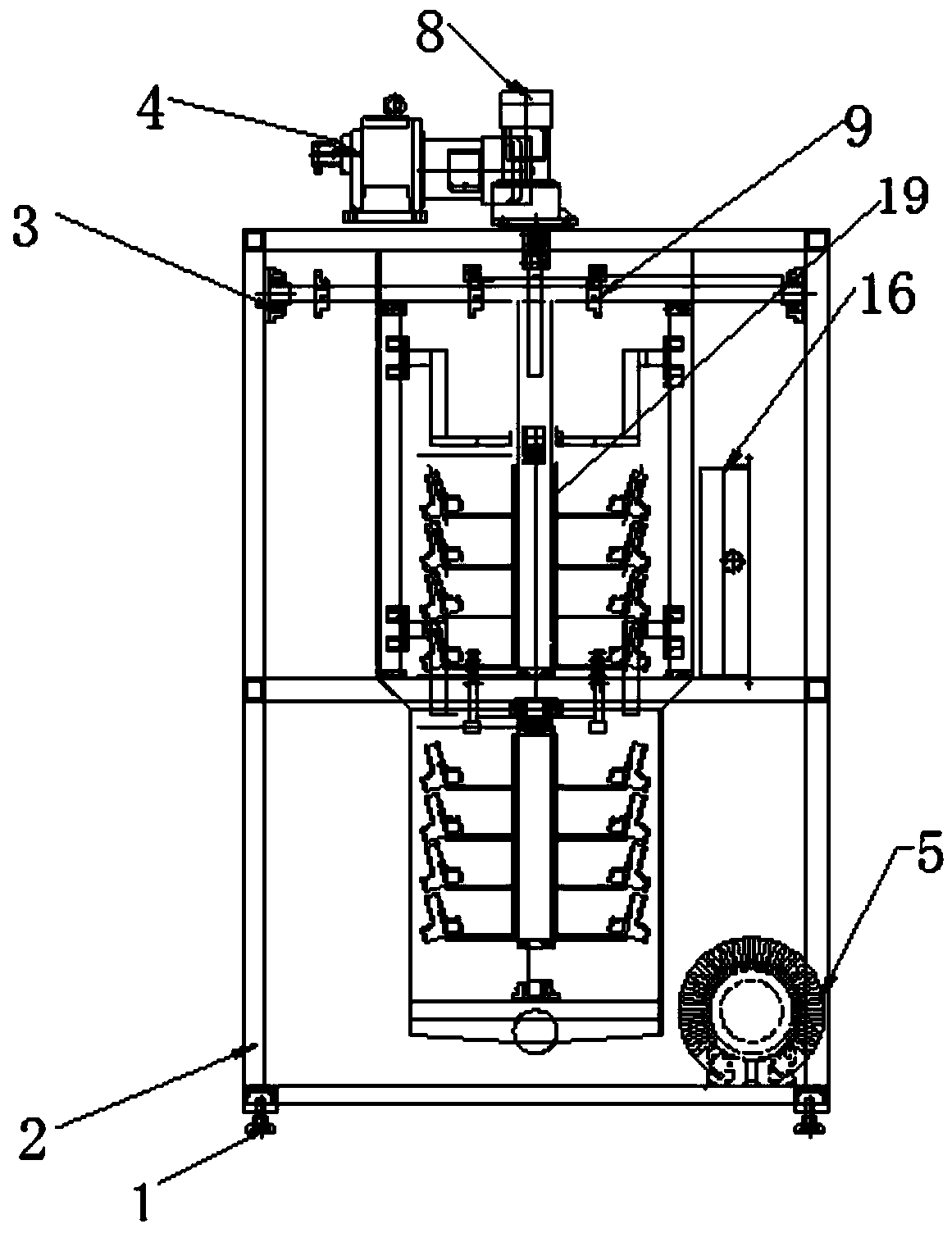
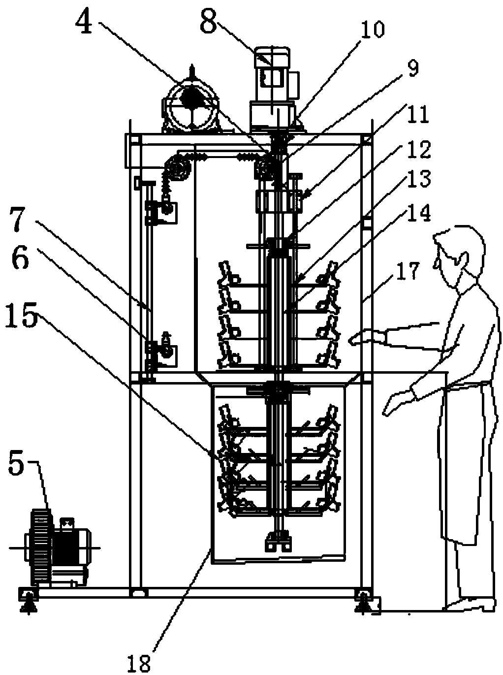
[0030] This embodiment discloses an oil immersion machine, which includes a lifting mechanism arranged at the top, a rotating mechanism, an oil immersion tank 18 arranged at the bottom, a blower mechanism, an observation window 17 and a frame 2 supporting the entire oil immersion machine;

[0031] The rotating mechanism includes a long shaft 19 that runs through the middle of the oil immersion machine from top to bottom, and multi-layer hooks 13 are longitudinally arranged on the long shaft 19, and the hooks 13 are used to place workpieces 15 to be cleaned;

[0032] Blowing mechanism comprises air knife 16 and air pump 5.

[0033] The hooks 13 are symmetrically distributed on both sides of the same cross-section of the long axis.

[0034] The lifting mechanism includes a lifting motor 4 and a lifting sprocket 9 arranged below it.

[0035] A slider 11 is sheathed on the long axis 19, and the slider 11 can move up and down along the optical axis 7, and a tapered roller bearing ...

Embodiment 2

[0041] This embodiment discloses a method of using the oil immersion machine described in Embodiment 1 to immerse a workpiece in oil, the method comprising the following steps:

[0042] S1: The operator hangs the workpieces on the hooks one by one, closes the observation window, and activates the one-key oil immersion key;

[0043] S2: The hook is lowered into the oil immersion tank for oil immersion treatment, and automatically rises to the designated position after the set time, and the rotating shaft starts to drive the hook to rotate and blow air;

[0044] S3: After the set time is up, the rotation and blowing will be stopped, and the equipment will alarm to remind the operator to unload the material, that is, the whole process of oil immersion and blowing is completed.

[0045] In S2, the set time for oil immersion treatment is 5-10 minutes.

[0046] In S3, the setting time of the rotation and blowing process is 3-8min.

[0047] The long axis can be rotated 360 degrees....


PUM


Abstract

The invention relates to the technical field of workpiece oil immersion, in particular to an oil immersion machine. The oil immersion machine comprises a lifting mechanism arranged on the top part, arotating mechanism, an oil immersion groove formed in the bottom part, an air blowing mechanism, an observation window, and a rack for supporting the whole oil immersion machine, wherein the rotatingmechanism comprises a long shaft penetrating through the middle part of the oil immersion machine from top to bottom; multiple layers of pothooks are longitudinally arranged on the long shaft, and areused for placing workpieces to be cleaned; and the air blowing mechanism comprises an air knife and an air pump. According to the oil immersion machine, the rotating mechanism is arranged and is provided with the liftable long shaft, the long shaft can rotate, in short, the oil immersion machine is provided with a coaxial lifting and rotating mechanism, and oil immersion and air blowing operationcan be accomplished in one machine, so that the production efficiency is greatly improved; and the oil immersion machine has the characteristics of low production cost, fast oil immersion speed, goodoil immersion effect, convenience in use, attractive appearance, reasonable structure, long service life and the like, and is the ideal oil immersion equipment.

Description

technical field [0001] The invention relates to the technical field of workpiece oil immersion, in particular to an oil immersion machine. Background technique [0002] The oil immersion treatment is to form an oil film on the surface of the workpiece, which can prevent the surface of the workpiece from being oxidized. At the same time, the surface of the part is not easy to rust after the oil immersion treatment and maintains its luster. At the same time, the oil immersion treatment can also remove the dirt on the surface of the workpiece Therefore, usually the oil immersion treatment is required after the metal workpiece is prepared, and the commonly used oil immersion treatment is completed by an oil immersion machine. After the oil immersion treatment is completed, the workpiece is often blown. [0003] In the traditional process, the oil immersion and blowing are processed by two separate machines, and the oil immersion treatment needs to be completed before entering t...

Claims


Application Information

Patent Timeline
Patent Type & Authority Applications(China)
IPC IPC(8): B05C3/09B05C13/02B05D3/04
CPCB05C3/09B05C13/02B05D3/0406
Inventor 徐健
Owner 苏州司达夫超声科技有限公司
Why Eureka
Try Eureka