Method for eliminating selective laser melting molding cracks of 7075 aluminum alloy

A technology of laser melting and aluminum alloy, which is applied in the field of 3D printing, can solve the problems of reduced density of parts and not particularly firm combination, and achieve the effect of suppressing thermal cracks and improving mechanical properties

Active Publication Date: 2019-02-01
SOUTH CHINA UNIV OF TECH
View PDF7 Cites 8 Cited by
  • Summary
  • Abstract
  • Description
  • Claims
  • Application Information

AI Technical Summary

Problems solved by technology

[0003] The purpose of the present invention is to overcome the deficiencies of the current selective laser melting technology, and provide a method for eliminating the processing cracks of 7075 aluminum alloy by selective laser melting technology and improving the density. It is mixed into the original powder of 7075 aluminum alloy as nucleation TiB 2 Submicron powder, so that the mixed powder suppresses the generation of thermal

Method used


Image

  • Method for eliminating selective laser melting molding cracks of 7075 aluminum alloy
  • Method for eliminating selective laser melting molding cracks of 7075 aluminum alloy
  • Method for eliminating selective laser melting molding cracks of 7075 aluminum alloy

Examples


Embodiment 1

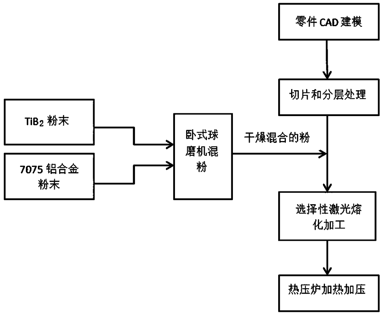
[0027] A method for eliminating cracks formed by selective laser melting of 7075 aluminum alloy, comprising the following steps:

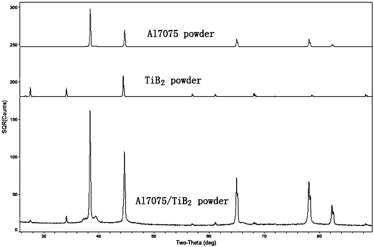
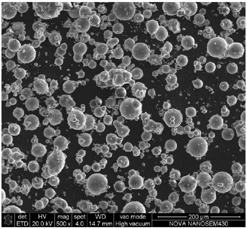
[0028] (1) In an argon-protected glove box, weigh 7075 aluminum alloy raw powder and TiB 2 Submicron powder (purity is 99%) for use, 7075 aluminum alloy powder and TiB 2 The mass ratio of submicron powder is 98.5:1.5;

[0029] (2) The weighed 7075 aluminum alloy powder and TiB 2 The submicron powder is placed in the ball mill tank in the argon protective glove box, and then the ball mill tank is locked, and high-purity argon gas is introduced after the ball mill tank is taken out;

[0030] (3) Put the ball mill jar into a horizontal ball mill for powder mixing. The ball mill speed is 200r / min, and the powder mixing time is 3h. Take out the ball mill jar, put it in a vacuum glove box, take out the mixed powder, and put the powder in a dry place. Dry in the oven at 80°C for 8 hours;

[0031] (4) Control the computer in the selective laser melting...

Embodiment 2

[0034] A method for eliminating cracks formed by selective laser melting of 7075 aluminum alloy, comprising the following steps:

[0035] (1) In an argon-protected glove box, weigh 7075 aluminum alloy raw powder and TiB 2 Submicron powder (purity is 99%) for use, 7075 aluminum alloy powder and TiB 2 The mass ratio of submicron powder is 97.0:3.0;

[0036] (2) The weighed 7075 aluminum alloy powder and TiB 2 The submicron powder is placed in the ball mill tank in the argon protective glove box, and then the ball mill tank is locked, and high-purity argon gas is introduced after the ball mill tank is taken out;

[0037] (3) Put the ball mill jar into a horizontal ball mill for powder mixing, the ball mill speed is 200r / min, and the powder mixing time is 5h, take out the ball mill jar, put it in a vacuum glove box, take out the mixed powder, put the powder in a dry place Dry in the oven at 80°C for 8 hours;

[0038] (4) Control the computer in the selective laser melting mold...


PUM


Abstract

The invention discloses a method for eliminating selective laser melting molding cracks of a 7075 aluminum alloy. The method comprises the following steps that (1), under a protective atmosphere, 7075aluminum alloy raw powder and TiB2 submicron powder are subjected to ball milling and powder mixing, and powder obtained after ball milling and powder mixing is taken out and dried; and (2), the powder dried in the step (1) is added into a powder storing cylinder of selective laser melting molding equipment, selective laser melting is conducted after working parameters of the selective laser melting molding equipment are set, a 7075 aluminum alloy molded part is obtained, and finally heating and pressurizing treatment is conducted on the 7075 aluminum alloy molded part. According to the method, the TiB2 submicron powder capable of promoting nucleation is added into the 7075 aluminum alloy raw powder, the selective laser melting molding periodic cracks of the 7075 aluminum alloy are eliminated, and the molded part is put into a heating and pressurizing furnace to be heated and pressurized to improve the density of the part.

Description

technical field [0001] The invention relates to the technical field of 3D printing, and more specifically relates to a method for eliminating cracks formed by selective laser melting of 7075 aluminum alloy. Background technique [0002] Selective laser melting technology is an additive manufacturing technology that has great advantages in manufacturing complex geometric shapes, increasing material utilization, reducing costs and achieving rapid cooling during production. Selective laser melting technology has good application prospects in aerospace, automobile manufacturing, biomedicine and other fields, and has become a research hotspot in the field of metal additive manufacturing in recent years. The samples processed by selective laser melting technology of 7075 aluminum alloy have very serious periodic thermal cracks, and the formed samples have poor mechanical properties such as strength, toughness and hardness. At present, scholars have used the method of electrostati...

Claims


Application Information

Patent Timeline
IPC IPC(8): B22F9/04B22F3/105B22F3/12B22F1/00C22C21/10C22C1/05C22C1/10B33Y50/02B33Y10/00
CPCC22C1/05C22C21/10B22F3/12B22F9/04B33Y10/00B33Y50/02B22F2009/043B22F2998/10B22F2999/00B22F10/00B22F2998/00B22F10/32B22F10/34B22F12/17B22F10/28B22F10/36B22F10/366B22F10/64B22F2201/11Y02P10/25
Inventor 李小强万达远赖佳明刘波屈盛官刘允中李晖云
Owner SOUTH CHINA UNIV OF TECH
Why Eureka
Try Eureka