
K wave band receiver noise temperature test method

A test method and noise temperature technology, applied in thermometers, receiver monitoring, thermometer applications, etc., can solve the problems of small black body load, difficult cold load coverage, small microwave devices, etc.

Active Publication Date: 2019-02-01
XINJIANG ASTRONOMICAL OBSERVATORY CHINESE ACADEMY OF SCI
View PDF4 Cites 4 Cited by
  • Summary
  • Abstract
  • Description
  • Claims
  • Application Information

AI Technical Summary

Problems solved by technology

Because the cold load is inconvenient to use during the observation process, and the noise temperature test generally adjusts the antenna elevation angle to 90 degrees before the observation, and the receiver engineer specially conducts the relevant test, which cannot be performed during the observation process
In addition, due to the different sizes of microwave components in different band receivers, the size of the feed source in the long centimeter band is too large. For example, the diameter of the feed source of the L-band receiver at Nanshan Station is 1.05 meters. Even using the cold and heat load method before observation is very difficult, because Difficult to provide a large enough cooling load to completely cover its feed port face
[0010] The method described in Chinese patent 201510569415.5 "A Noise Temperature Test System and Method Applicable to Terahertz Receivers" is to use a room temperature blackbody load (27°C) and a high temperature blackbody load (999°C) to test the noise temperature of the receiver. The high-temperature blackbody load (999°C) required at least one cavity that can provide this temperature can be satisfied. In addition, the receiver and test method described in this method work in the terahertz band, and the microwave devices in this band are small. The required black body load volume is also small. If you encounter a microwave device with a large centimeter band (such as the L-band receiver feed at Nanshan Station), it is also difficult to provide a large enough high-temperature load to completely cover the receiver feed surface.

Method used


Image

  • K wave band receiver noise temperature test method
  • K wave band receiver noise temperature test method
  • K wave band receiver noise temperature test method

Examples


Embodiment

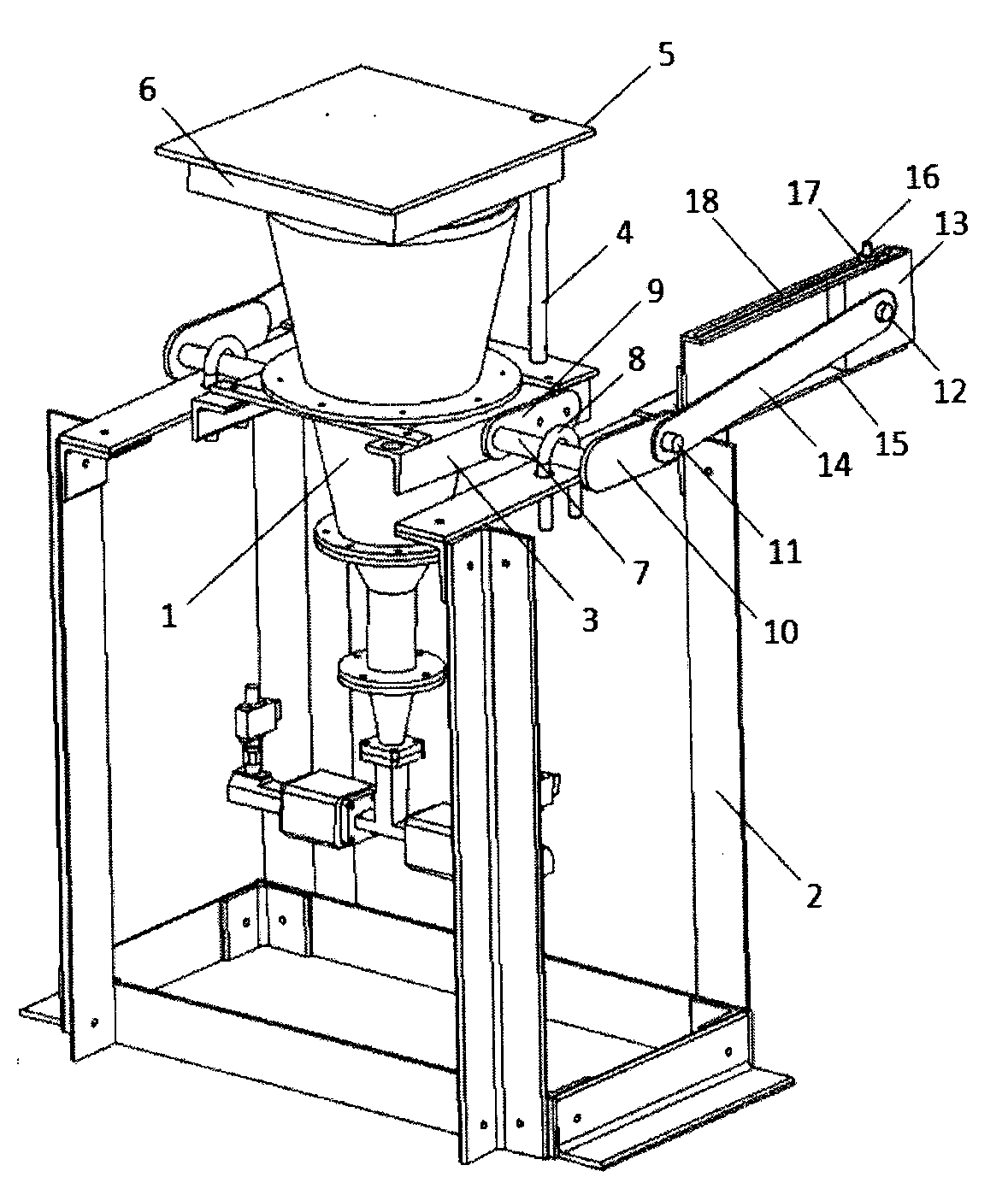
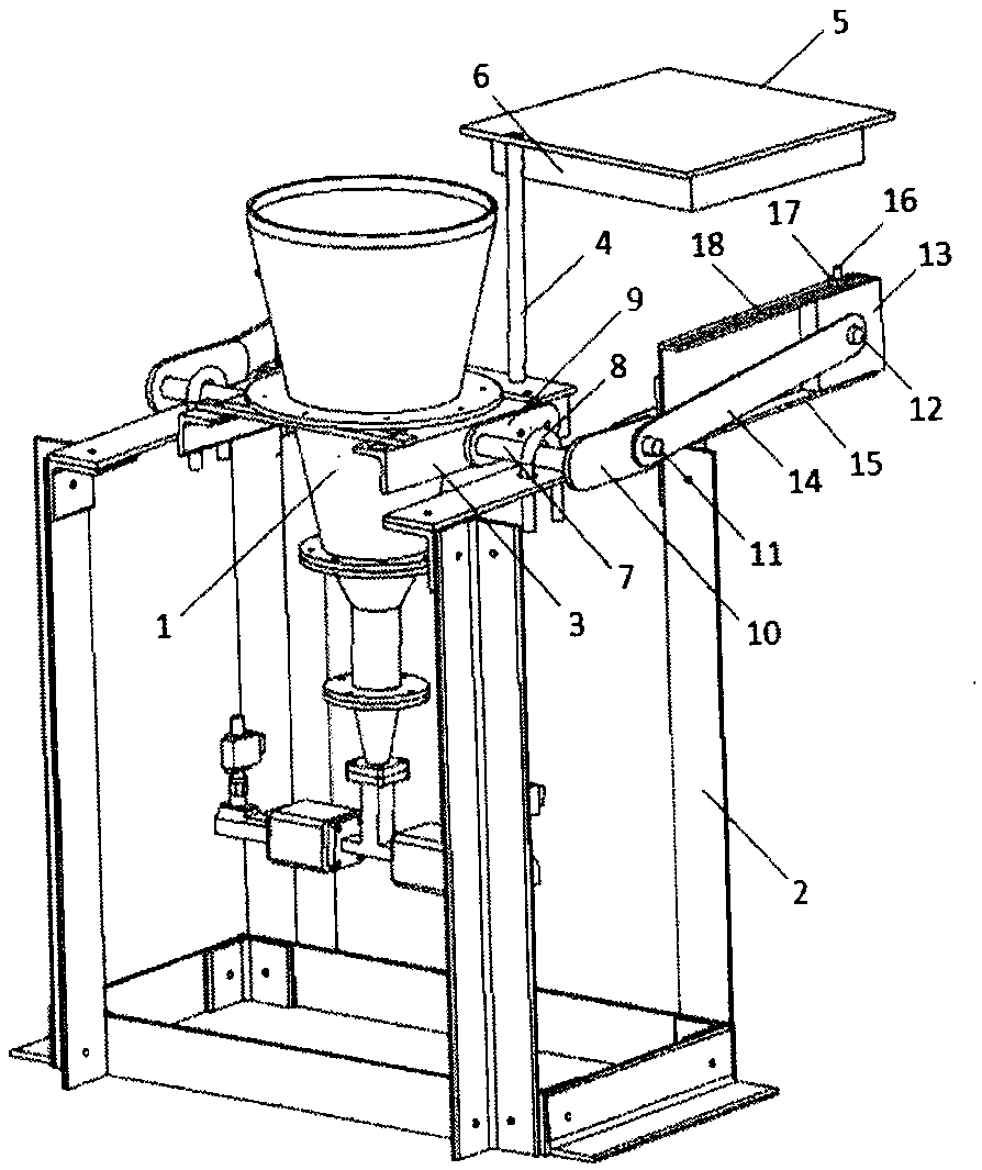
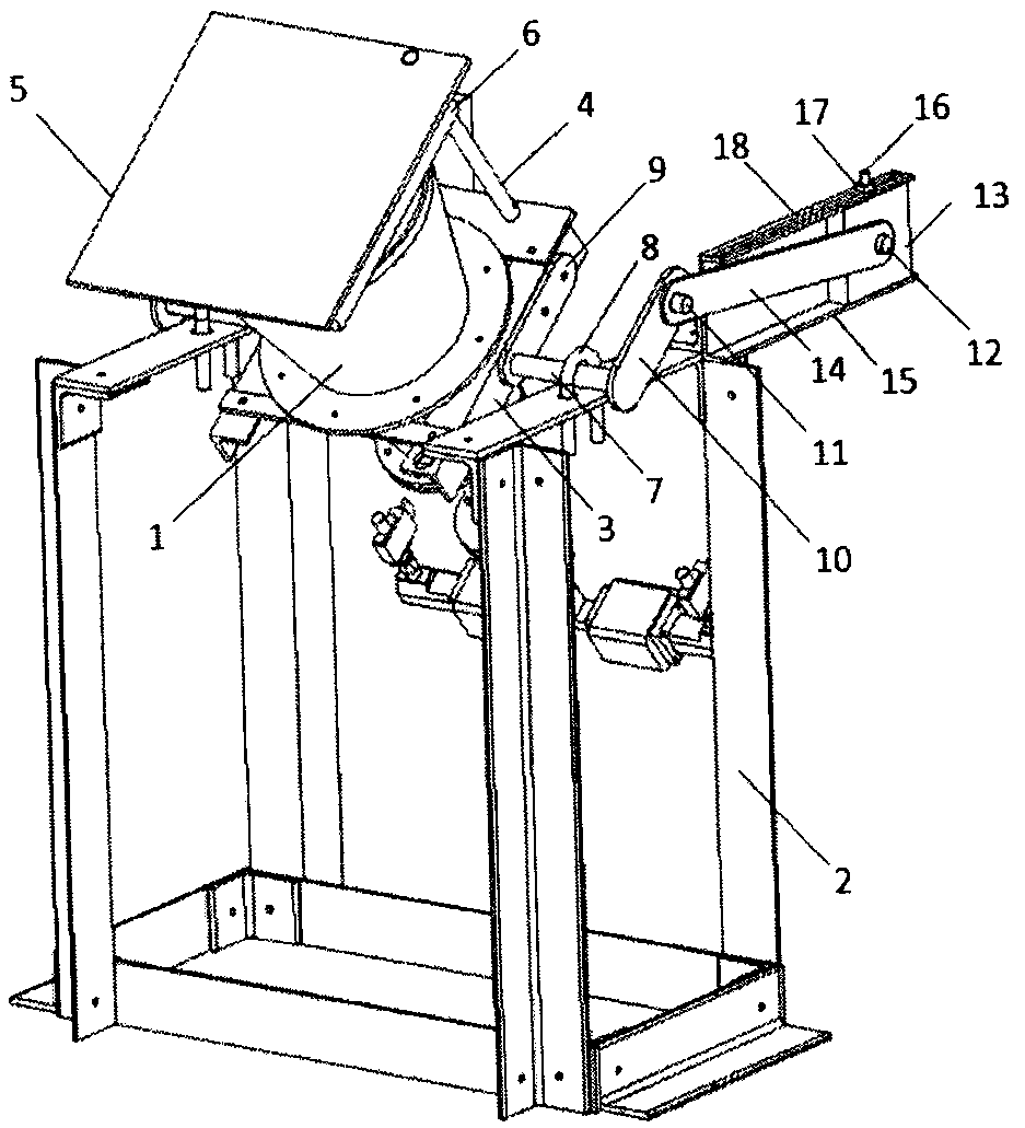
[0035] A kind of K-band receiver noise temperature testing method of the present invention, the device that this method relates to is by K-band receiver, pedestal, fixed frame, rotating shaft, rotating table, normal temperature blackbody, rotating shaft, U-bolt, The first rotating shaft fixing plate, the second rotating shaft fixing plate, the first fixing pin, the second fixing pin, a slider, a slider connecting rod, a sliding guide rail, an angle fixing screw, an angle fixing nut, and an angle fixing chute, The lower part of the feed flange of the K-band receiver 1 is connected to the fixed frame 3, the rear end of the fixed frame 3 is connected to the bottom end of the rotating shaft 4, the top end of the rotating shaft 4 is connected to the rotating table 5, and the lower side of the rotating table 5 is connected to the normal temperature blackbody 6 , the rotating shaft 7 is fixed on the top of the seat frame 2 through U-shaped bolts 8, the side of the fixing frame 3 is in...


PUM


Abstract

The invention relates to a K wave band receiver noise temperature test method. A device related in the method is composed of a K wave band receiver, a pedestal, a fixed frame, a rotary shaft, a turn table, a normal temperature black body, a rotating shaft, a U-shaped bolt, a first rotating shaft fixing board, a second rotating shaft fixing board, a first fixing pin, a second fixing pin, a slidingblock, a sliding block connection rod, a sliding guide rail, an angle fixing threaded rod, an angle fixing nut and angle fixing sliding chute. In the method, a cold load which is difficult to operateis replaced by cold air; a test device can introduce or remove a normal temperature black body load at a feed source port surface, also can discretionarily adjust the K wave band receiver and a beam direction thereof in elevation of 0-90 degrees, and can complete measurement and calculation of noise temperature of the receiver in combination with sky brightness temperature corresponding to the K wave band under the current elevation. The method simulates performing quick noise temperature test for the K wave band receiver in an observation process, avoids potential safety hazards caused by that an antenna elevation must be kept at 90 degrees for test and low-temperature liquid nitrogen is used in the conventional cold and hot load method, and promotes test efficiency and safety remarkably.

Description

technical field [0001] The invention relates to an accurate and rapid noise temperature test method for a K-band receiver during observation, which is specially used for the noise temperature test of the K-band receiver. Background technique [0002] Radio astronomy is a discipline that uses radio telescopes to observe radio waves radiated from cosmic celestial bodies, and microwave receivers are equipment specially used in radio telescopes to receive radio signals. Regarding the definition of the microwave receiver, some regard the feed as a part of the receiver, and some consider the feed as a part of the antenna system. The original radio signal is reflected once by the main reflector of the antenna, then reflected twice by the sub-reflector to the feed source of the receiver, and then transmitted to the data terminal after passing through the receiver's orthogonal mode coupler, low noise amplifier and other devices. [0003] The main technical index of microwave receive...

Claims


Application Information

Patent Timeline
IPC IPC(8): H04B17/29G01K13/00
CPCH04B17/29G01K13/00
Inventor 王凯王洋曹亮闫浩李笑飞陈卯蒸马军李健刘艳玲宁云炜
Owner XINJIANG ASTRONOMICAL OBSERVATORY CHINESE ACADEMY OF SCI
Learn More