Construction process of concrete steel formwork

A construction technology and steel formwork technology, which is applied in the direction of manufacturing tools, mold separation devices, ceramic molding machines, etc., can solve the problems of unimproved concrete fixing and form removal process, easy cracking and damage of concrete building parts, pockmarked concrete surface building parts, etc. problems, to achieve the effect of improving the molding quality and strength, not easy to rust and oxidize, and the surface is smooth and beautiful

Inactive Publication Date: 2019-02-05
GUANGDONG BOZHILIN ROBOT CO LTD
View PDF0 Cites 3 Cited by
  • Summary
  • Abstract
  • Description
  • Claims
  • Application Information

AI Technical Summary

Problems solved by technology

[0002] Concrete steel formwork is a steel formwork used for concrete pouring and forming. After the steel formwork structure concrete is poured and formed, an ideal rough interface can be formed. In construction projects, steel formwork is used for its multiple uses and beautiful concrete pouring. Widely used, in the existing concrete steel formwork construction technology, there is no improvement in the concrete fixing and form removal process, the concrete is easy to remain, causing environmental pollution and corrosion to the steel formwork, and in the existing concrete steel formwork construction technology, Concrete is internally hardened in a short period of time, and it is prone to not being compacted. After the formwork is removed, the surface of the concrete will appear pitted, which will affect the overall project quality. At the same time, the existing concrete steel formwork construction process is not good enough for the concrete curing process. Concrete building parts are easy to crack and damage, and the water loss is serious. Therefore, the present invention proposes a construction process of concrete steel formwork to solve the problems existing in the prior art

Method used


Image

  • Construction process of concrete steel formwork

Examples


Embodiment Construction

[0036] In order to make the technical means, objectives, and effects of the invention easy to understand, the present invention will be further described below in conjunction with specific embodiments.

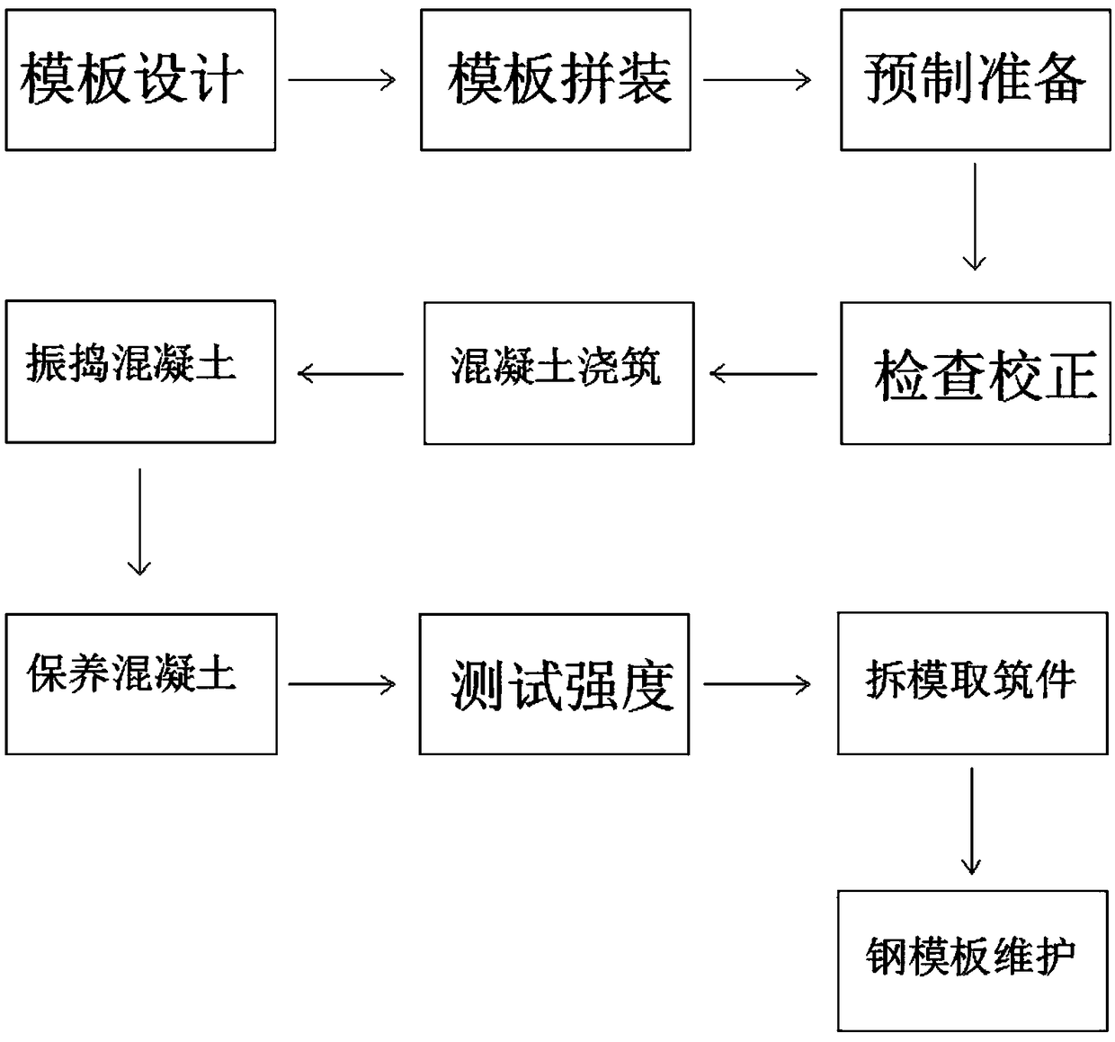
[0037] Construction technology of a concrete steel formwork

[0038] Step 1: Template Design

[0039] According to the type and characteristics of the project structure and on-site construction conditions, design the steel formwork, determine the plane layout of the steel formwork, the specifications, quantity, and arrangement size of the vertical and horizontal keels, the type and spacing of column hoops, the distance between beam and slab supports, formwork assembly form and connection Large-scale joints, the formwork assembly form is one of in-place assembly or prefabricated assembly, and check the strength, stiffness and stability of the steel formwork support, and draw a full set of steel formwork design drawings, including formwork plan, block diagram, assembly drawing, ...


PUM


Abstract

The invention discloses a construction process of a concrete steel formwork. The construction process of the concrete steel formwork comprises the following steps of formwork design, formwork assembling, formwork splicing, prefabrication preparation, inspection and correction, concrete pouring, concrete vibrating, concrete curing, strength testing, cast part taking through formwork disassembling,and steel formwork maintenance. According to the construction process of the concrete steel formwork, a column formwork and column loops are mounted, an upper end formwork and a lower end formwork arefastened through screws, and fasteners such as U-shaped clamps and disc-shaped fasteners of hook bolt outer pads are used for fastening, so that deformation of the whole steel formwork is avoided inthe construction process, and concrete can be fixed more firmly; a demolding isolation agent of the steel formwork is processed, so that concrete is prevented from being left on the steel formwork after demolding; water is poured for wetting, so that the situation that moisture of the concrete is absorbed by the steel formwork, and consequentially, the concrete is not compact, and a pitted surfaceis caused is avoided, and the forming quality and strength of the concrete are improved; and meanwhile, a plastic film is used for maintenance in the seventh step, so that water losses are avoided while heat preservation is achieved.

Description

technical field [0001] The invention relates to the field of building construction, in particular to a construction technique of a concrete steel formwork. Background technique [0002] Concrete steel formwork is a steel formwork used for concrete pouring and forming. After the steel formwork structure concrete is poured and formed, an ideal rough interface can be formed. In construction projects, steel formwork is used for its multiple uses and beautiful concrete pouring. Widely used, in the existing concrete steel formwork construction technology, there is no improvement in the concrete fixing and form removal process, the concrete is easy to remain, causing environmental pollution and corrosion to the steel formwork, and in the existing concrete steel formwork construction technology, Concrete is internally hardened in a short period of time, and it is prone to not being compacted. After the formwork is removed, the surface of the concrete will appear pitted, which will a...

Claims


Application Information

Patent Timeline
Patent Type & Authority Applications(China)
IPC IPC(8): B28B7/26B28B1/093B28B1/04B28B13/02B28B13/06B28B7/38
CPCB28B1/045B28B1/093B28B7/26B28B7/382B28B13/0235B28B13/065
Inventor 孙军杨泓斌高国恒闫学超林浩忠
Owner GUANGDONG BOZHILIN ROBOT CO LTD
Why Eureka
Try Eureka