Vacuum robot, vacuum motor for vacuum robot, and production method of said vacuum motor

a technology for vacuum robots and production methods, applied in manufacturing tools, packaging goods types, transportation and packaging, etc., can solve the problems of increasing the body size of the robot including the motor portion, extremely reducing electromagnetic power, and increasing the size of the robo

Inactive Publication Date: 2011-05-31
YASKAWA DENKI KK
View PDF1 Cites 27 Cited by
  • Summary
  • Abstract
  • Description
  • Claims
  • Application Information

AI Technical Summary

Benefits of technology

[0021]The preferred embodiments of the present invention have been developed in view of the above-mentioned and / or other problems in the related art. The preferred embodiments of the present invention can significantly improve upon existing methods and / or apparatuses.
[0022]Among other potential advantages, some embodiments according to the present invention can provide a small, lightweight and highly-reliable work transferring robot capable of having a thin can material of a stator portion, decreasing an electromagnetic gap and preventing dusting and corrosion.
[0050]According to the preferred embodiment of the present invention, the following effects can be obtained.
[0051](1) The space in which the stator portion exists nearly maintains the initial vacuum status created when the motor was produced, and the pressure difference between the pressure of the space and the pressure of the rotor portion in the can (chamber space such as a transferring chamber in which the rotor portion or the robot arm is used) is small. Thus, the pressure to be applied to the can 16 can be reduced, which makes it possible to reduce the thickness of the can. As result, the body diameter of the robot can be decreased.
[0052](2) When it becomes possible to reduce the thickness of the can and reduce the electromagnetic gap, it can be expected to increase the electromagnetic power, which in turn can reduce the size and the weight of the motor portion. Accordingly, the body diameter of the robot can be reduced.
[0053](3) Since the space of the stator portion is in a vacuum state, the winding of the stator portion is hard to oxidize thus preventing a possible short circuit due to the dusting and / or the dew concentration, which in turn can enhance the reliability of the motor and robot.

Problems solved by technology

(1) It can be expected to produce an effect that even if the stator portion generates dust, the dust will not be introduced into the inner portion of the robot and / or into the vacuum chamber. However, a force (which is approximately the same as atmospheric pressure) caused by the pressure difference between the atmospheric pressure environment and the vacuum chamber is kept applied to the can separating the atmospheric pressure environment and the vacuum chamber, and therefore it is necessary to prevent the deformation and / or the breakage of the can. As a result, it is naturally required to maintain the strength of the can by increasing the thickness of the material of the cylindrical member constituting the can. This results in an increased size of the can, which in turn results in an increased body size of the robot including the motor portion.
(2) In order to increase the electromagnetic power of the motor, it is very effective to decrease the distance (electromagnetic gap) between the winding of the stator and the magnet of the rotor portion. However, since the can is located between the winding and the magnet, the electromagnetic gap increases as the thickness of the can increases, resulting in extremely decreased electromagnetic power. As is well known, keeping the electromagnetic gap even and narrow has a great effect on the motor performance.
(3) Although the winding of the stator portion is disposed at the atmospheric side, since the winding is made of a metallic wire, it can be oxidized by the moisture contained in the atmosphere to be rusted and corroded due to the dusting or the dew condensation. This may develop to break the insulation layer of the winding, causing the short circuit, which in turn results in an inoperable wafer transferring robot.

Method used


Image

  • Vacuum robot, vacuum motor for vacuum robot, and production method of said vacuum motor
  • Vacuum robot, vacuum motor for vacuum robot, and production method of said vacuum motor
  • Vacuum robot, vacuum motor for vacuum robot, and production method of said vacuum motor

Examples


Embodiment Construction

[0062]In the following paragraphs, some preferred embodiments of the invention will be described by way of example and not limitation. It should be understood based on this disclosure that various other modifications can be made by those in the art based on these illustrated embodiments.

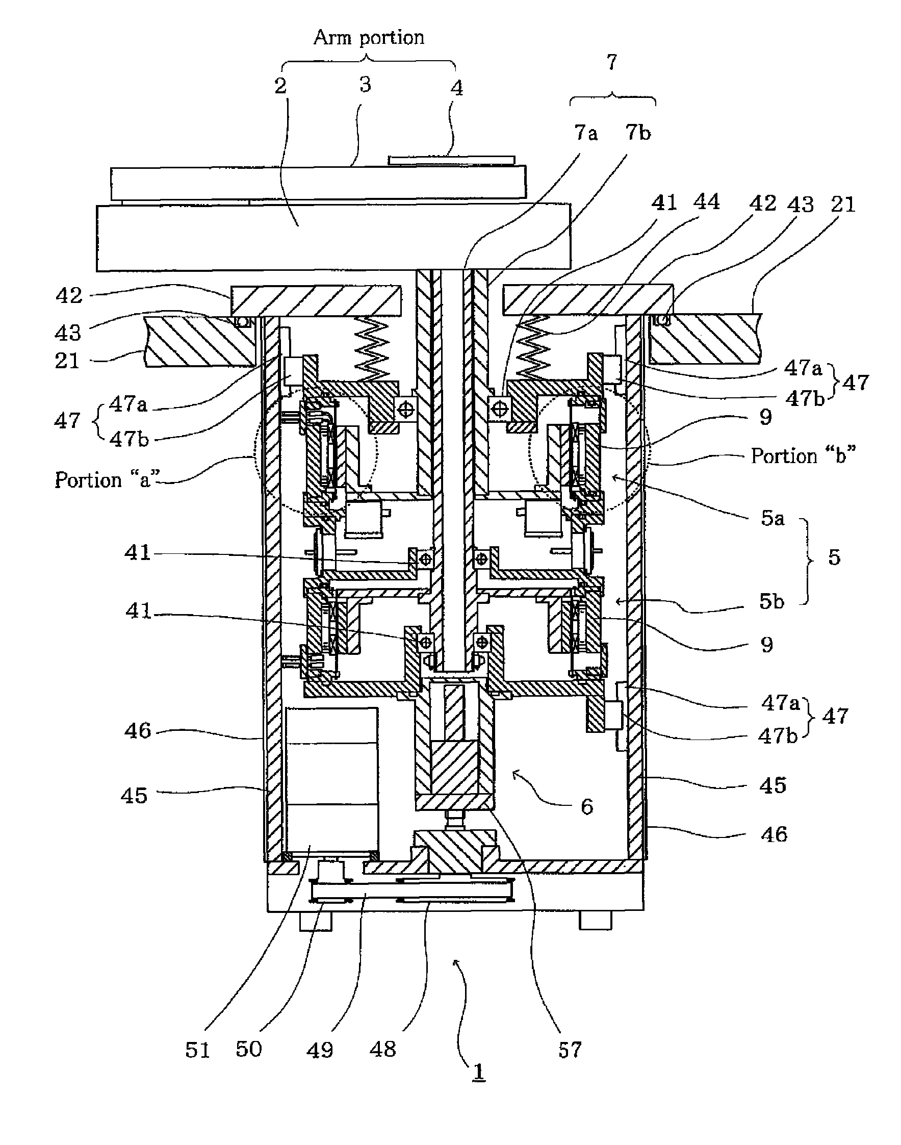
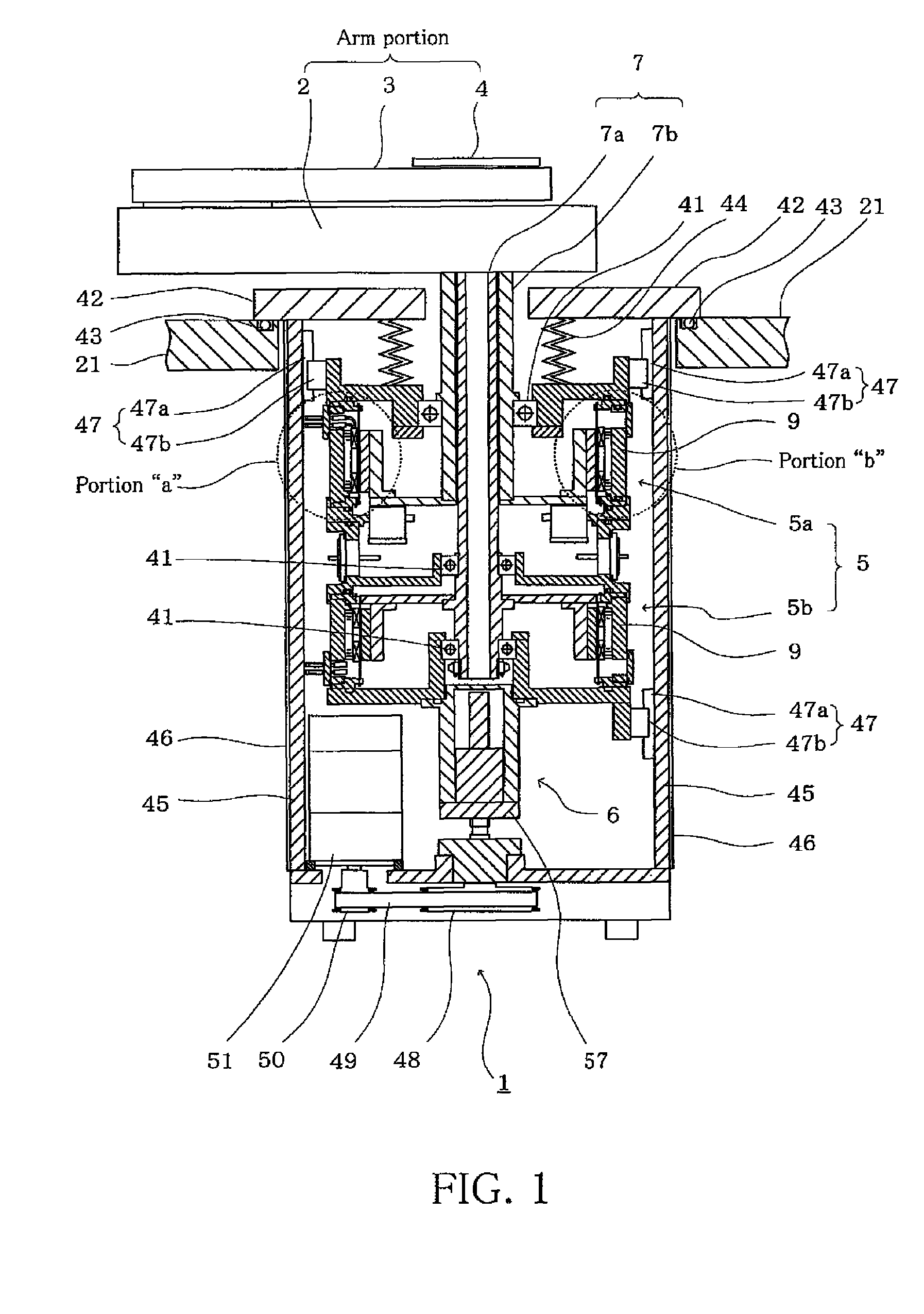
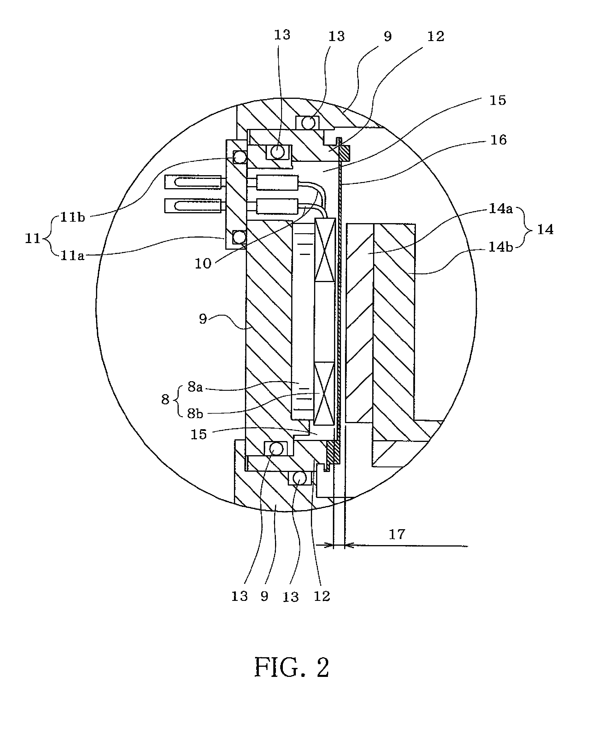
[0063]An embodiment of the present invention will be explained with reference to the attached drawings. FIG. 1 is a side cross-sectional view of a vacuum robot showing an embodiment of the present invention. FIGS. 2 and 3 each shows an enlarged view of the principal portion (portion “a” and “b”) shown in FIG. 1.

[0064]In FIG. 1, the reference numeral “1” denotes a work transferring robot which is the same as the wafer transferring robot 1 shown in FIG. 5. The same reference numeral is allotted to the corresponding portion. The work transferring robot 1 generally includes an arm portion including robot arms 2 and 3 and a hand 4, and a motor portion 5 for rotatably driving the arm portion. The motor por...


PUM


Abstract

A vacuum robot includes an arm portion on which a work is to be disposed under a reduced pressure environment and a motor portion for rotatably driving the arm portion, the vacuum robot being configured to transfer the work by causing a rotational movement of the arm portion by the motor portion. The motor portion comprises a rotor portion connected to the arm portion, a stator portion disposed at an external periphery of the rotor portion, a housing disposed under an atmospheric pressure environment, and a thin cylindrical can disposed in an electromagnetic gap formed between the rotor portion and the stator portion and secured to the housing so that the stator portion is air-tightly encapsulated in a space formed by the housing and the can. The space is maintained in a depressurized state by a seal.

Description

[0001]This application claims priority under 35 U.S.C. §119 to Japanese Patent Application No. 2006-153738 filed on Jun. 1, 2006, the entire disclosure of which is incorporated herein by reference in its entirety.BACKGROUND OF THE INVENTION[0002]1. Field of the Invention[0003]The present invention relates to a vacuum robot, a vacuum motor for use in the vacuum robot, and a production method of the vacuum robot. More specifically, some preferred embodiments of the present invention relate to a work transferring vacuum robot for transferring a work in a vacuum environment, such as, e.g., in a semiconductor production apparatus or a crystal liquid production apparatus, a vacuum motor to be preferably used for driving a work transferring arm of the work transferring vacuum robot, a production method of the vacuum motor, and a work processing method using the vacuum robot.[0004]2. Description of the Related Art[0005]The following description sets forth the inventor's knowledge of related...

Claims


Application Information

Patent Timeline
Patent Type & Authority Patents(United States)
IPC IPC(8): H01L21/677
CPCB25J9/126H01L21/68707B25J19/0079B25J9/04B25J19/00
Inventor NAKAMURA, TAKAYUKINOGUCHI, TADATAKAKUSAMA, YOSHIHIRO
Owner YASKAWA DENKI KK
Why Eureka
Try Eureka