Resin transfer molding (RTM) method for composite blade
A molding method and composite material technology, applied in the field of resin matrix composite material liquid molding, can solve the problems of less structural interweaving points, structural stability, prefabricated body slip, blade structural deformation, etc. The degree of displacement and the effect of increasing the injection speed
- Summary
- Abstract
- Description
- Claims
- Application Information
AI Technical Summary
Problems solved by technology
Method used
Image

Examples
Embodiment 1
[0055] The blade prefabricated body 10 is a variable thickness 2.5D woven structure fan blade prefabricated body, the material is CCF800, and the fiber volume content of the material is 55%±3%; CCF800 is a T800 grade carbon fiber fabric with a specification of 12K produced by Shandong Weihai Development Company , the injection resin adopts PR520 high-toughness liquid molding resin from CYTEC Company. The external dimensions of the blade body 1 are: 750mm×300mm (length×width), and the external dimensions of the blade prefabricated body are 800mm×340mm (length×width). There is a margin of 20mm around the body. The specific molding steps are as follows:
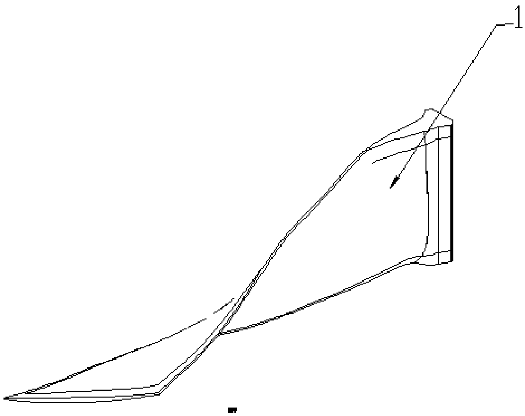
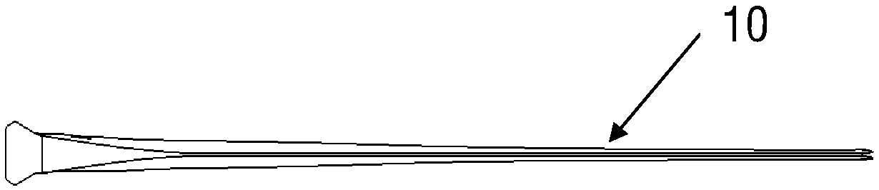
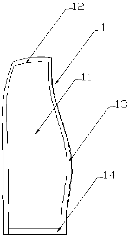
[0056] 1) The blade 1 is composed of a blade body 11 and a blade margin area 12, the blade margin area 12 is composed of a blade tenon margin area 13 and a blade edge margin area 14, and the blade prefabricated body 10 is an intermediate body of the blade 1 before RTM molding;
[0057] 2) The molding die 4 is processed from a P2...
Embodiment 2
[0068] The blade prefabricated body 10 is a variable thickness 2.5D woven structure fan blade prefabricated body, the material is T700, and the fiber volume content of the material is 58% ± 3%; T700 is a T700 grade carbon fiber fabric with a specification of 12K produced by Toray Corporation of Japan The resin used for injection is ACTECH1304 high-toughness liquid molding resin of AVIC Composites Co., Ltd. The overall dimensions of the blade body 1 are: 720mm×260mm (length×width), and the overall dimensions of the blade preform are 780mm×320mm (length×width) ), leaving a margin of 30mm around the blade prefabricated body, the specific forming steps are as follows:
[0069] 1) The blade 1 is composed of a blade body 11 and a blade margin area 12, the blade margin area 12 is composed of a blade tenon margin area 13 and a blade edge margin area 14, and the blade prefabricated body 10 is an intermediate body of the blade 1 before RTM molding;
[0070] 2) The molding die 4 is proce...
PUM
| Property | Measurement | Unit |
|---|---|---|
| Height | aaaaa | aaaaa |
Abstract
Description
Claims
Application Information
 - R&D
- Intellectual Property
- Life Sciences
- Materials
- Tech Scout
- Unparalleled Data Quality
- Higher Quality Content
- 60% Fewer Hallucinations
Browse by: Latest US Patents, China's latest patents, Technical Efficacy Thesaurus, Application Domain, Technology Topic, Popular Technical Reports.
© 2025 PatSnap. All rights reserved.Legal|Privacy policy|Modern Slavery Act Transparency Statement|Sitemap|About US| Contact US: help@patsnap.com