
Cage type foldable multi-rotor heavy-duty large unmanned aerial vehicle

A technology of unmanned aerial vehicles and multi-rotors, which is applied in the aviation field, can solve the problems of short flight time, low load capacity, and the inability to carry out long-term flight with heavy load, and achieve long flight time, large load capacity, and easy parking and transportation. Effect

Pending Publication Date: 2019-02-05
广东电网能源发展有限公司
View PDF0 Cites 4 Cited by
  • Summary
  • Abstract
  • Description
  • Claims
  • Application Information

AI Technical Summary

Problems solved by technology

[0002] At present, the aircraft used in the world mainly include helicopters, fixed-wing aircraft, rotorcraft, powered parachutes, and powered delta wings. However, in recent years, a new type of aircraft has emerged, which is called multi-rotor aircraft in China. The mechanical structure is simple, easy to make, and the control performance is good. It can easily realize vertical take-off, landing, hovering and other actions, but its low load capacity and short sailing time make it impossible to carry out long-term sailing with heavy loads; it is still blank in this field of application , thus inventing a set of heavy-duty, foldable heavy-duty large-scale multi-rotor drones

Method used


Image

  • Cage type foldable multi-rotor heavy-duty large unmanned aerial vehicle
  • Cage type foldable multi-rotor heavy-duty large unmanned aerial vehicle
  • Cage type foldable multi-rotor heavy-duty large unmanned aerial vehicle

Examples


Embodiment Construction

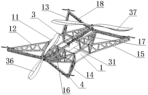
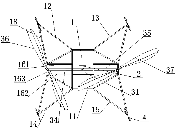
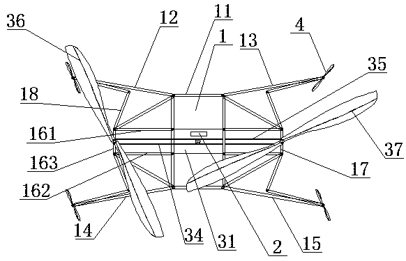
[0018] The present invention is described in detail below in conjunction with the accompanying drawings: a cage-type foldable multi-rotor heavy-duty large-scale unmanned aerial vehicle, comprising a cage body 1, a flight control device 2, a lift device 3, and an attitude control device 4; a cage body 1 Comprising a square frame 11, a left front movable arm 12, a right front movable arm 13, a left rear movable arm 14 and a right rear movable arm 15; a left support frame 16 and a right support frame 17 extend from the left and right sides of the square frame 11 middle part; the left front movable arm 12, the roots of four of the front right movable arm 13, the left rear movable arm 14 and the right rear movable arm 15 are loosely installed on the four end angles of the cage body 1 respectively; The positions are all connected with the left support frame 16 by the folding frame 18; the tip positions of the right front movable arm 13 and the right rear movable arm 15 are all connec...


PUM


Abstract

The invention relates to a cage type foldable multi-rotor heavy-duty large unmanned aerial vehicle, and belongs to the technical field of aviation. The cage type foldable multi-rotor heavy-duty largeunmanned aerial vehicle includes a cage airframe, a flight control device, a lift device and an attitude control device, four folding frames are unfolded, and a front left movable arm, a front right movable arm, a rear left movable arm and a rear right movable arm are unfolded; an engine is started, the engine drives left and right rotating shafts to rotate through a synchronous belt, and the leftrotating shaft and the right rotating shaft drive a large left propeller and a large right propeller to rotate crosswise; by increasing the rotating speed of the engine, the large left propeller andthe large right propeller speed up to produce larger lift, the unmanned aerial vehicle takes off vertically, and the flying attitude of the unmanned aerial vehicle is adjusted by adjusting the attitude control device; and during landing, the rotating speed of the engine is lowered, the unmanned aerial vehicle slowly lands vertically, and balance of the unmanned aerial vehicle is adjusted by adjusting the attitude control device. According to the cage type foldable multi-rotor heavy-duty large unmanned aerial vehicle, the airframe is made of an aluminum alloy or a titanium alloy by welding, andcan be folded to facilitate parking and transportation of the unmanned aerial vehicle; and the lift is large, stability is good, and the cage type foldable multi-rotor heavy-duty large unmanned aerial vehicle is suitable for lifting and hanging operation.

Description

technical field [0001] A cage-type foldable multi-rotor heavy-duty large unmanned aerial vehicle belongs to the field of aviation technology, and in particular relates to a cage-type foldable multi-rotor heavy-duty large unmanned aerial vehicle. Background technique [0002] At present, the aircraft used in the world mainly include helicopters, fixed-wing aircraft, rotorcraft, powered parachutes, and powered delta wings. However, in recent years, a new type of aircraft has emerged, which is called multi-rotor aircraft in China. The mechanical structure is simple, easy to manufacture, and the control performance is good. It can easily realize vertical take-off, landing, hovering and other actions, but its low load capacity and short sailing time make it impossible to carry out long-term sailing with heavy loads; it is still blank in this field of application , thus inventing a set of heavy-duty, foldable heavy-duty large-scale multi-rotor drones. Contents of the invention ...

Claims


Application Information

Patent Timeline
Patent Type & Authority Applications(China)
IPC IPC(8): B64C1/30B64C27/08B64C27/12B64D27/24B64D31/00
CPCB64C1/30B64C27/08B64C27/12B64D27/24B64D31/00B64U10/10B64U50/19
Inventor 蔡敬雄
Owner 广东电网能源发展有限公司
Learn More