
A combination of active and passive oil static eliminator

A static eliminator and combined technology, applied in the direction of static electricity, instruments, electrical components, etc., can solve the problems of easy piercing of pipelines, leakage of static electricity, explosion hazards, etc., and achieve easy ionization discharge, eliminate static electricity, and avoid explosion and explosion. dangerous effect

Active Publication Date: 2021-02-09
CHINA PETROLEUM & CHEM CORP +1
View PDF14 Cites 0 Cited by
  • Summary
  • Abstract
  • Description
  • Claims
  • Application Information

AI Technical Summary

Problems solved by technology

The method of installing a pipeline static eliminator is often used in large oil pipelines. In thin oil pipelines, static electricity is more likely to be generated due to the slender pipeline, and the oil flow rate in the pipeline is high. The method of grounding the metal shell to leak static electricity is not suitable. Pipeline static elimination equipment, the discharge needle set is easy to pierce the pipeline, resulting in damage to the pipeline; when there is no oil in the pipeline or the fluid cross section of the oil in the pipeline is smaller than the diameter of the pipeline, in both cases the pipeline will There is a large amount of oil and gas remaining. At this time, the discharge of the discharge needle is likely to cause danger.
It cannot adapt to the situation where the charge in the pipeline changes greatly, and ensures the safety when the charge is small, and timely leaks static electricity
In addition, the high-voltage discharge process of the discharge needle is likely to cause explosion hazards, so it is necessary to design an oil static eliminator that combines active and passive

Method used


Image

  • A combination of active and passive oil static eliminator
  • A combination of active and passive oil static eliminator
  • A combination of active and passive oil static eliminator

Examples


Embodiment Construction

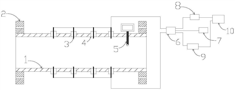
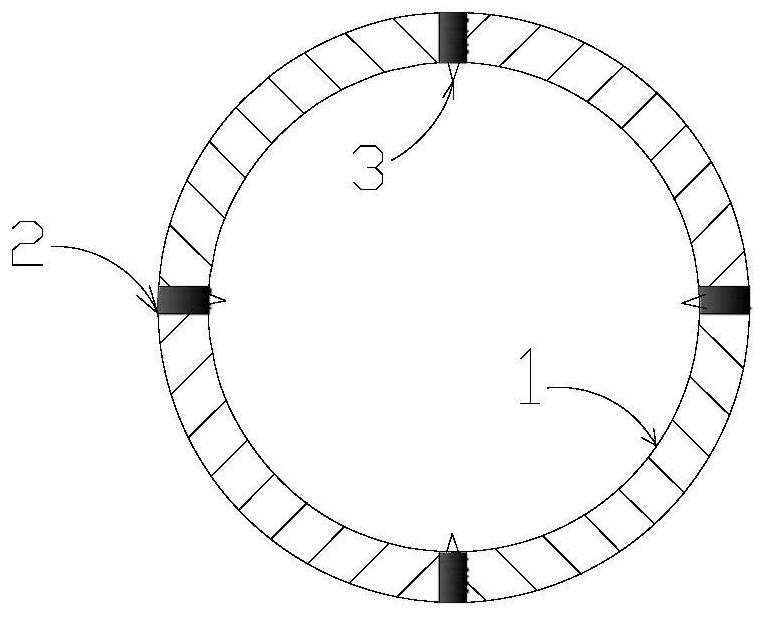
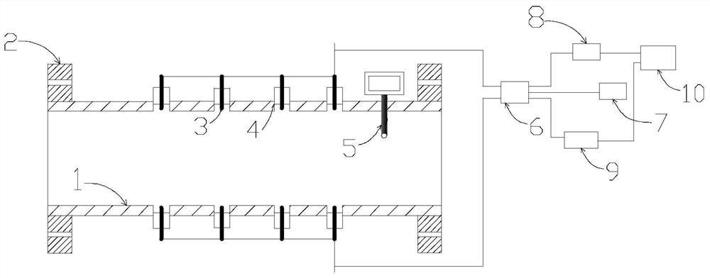
[0020] An active and passive oil static eliminator, including pipeline 1, connecting flange 2, discharge needle 3, insulating block 4, oil charge density monitor 5, switch 6, grounding device 7, positive voltage Generating device 8 , negative voltage generating device 9 and control device 10 . The pipeline 1 is the main body of the oil static eliminator, the diameter is equal to the diameter of the oil pipeline, and is connected in series to the oil pipeline through the connecting flange 2 . The insulating block 4 wraps the discharge needle 3, and the discharge needle 3 is arranged on the main body of the pipeline 1. The oil charge density monitor 5 extends into the pipeline oil to measure the charge density of the oil. The discharge needle 3 is connected to the switch 6 through a wire, and the switches are respectively connected to the grounding device 7, the positive voltage generating device 8 and the negative voltage generating device 9, and the control device 10 controls ...


PUM


Abstract

The invention provides an active and passive oil static eliminator, which mainly solves the problem that the oil static electricity in the thin oil pipeline cannot be eliminated. It includes pipelines, connecting flanges, discharge needles, insulating blocks, and oil charge density. Monitors, switches, grounding devices, positive voltage generators, negative voltage generators, and controls. The oil static eliminator is connected to the pipeline in series through the connecting flange; the insulation module ensures that the discharge needle and the pipeline will not be broken down by high voltage; the oil charge density monitor is used to monitor the static electricity of the oil in the pipeline, and the monitoring data Upload to the control module; the control device controls the output voltage of the positive voltage generator and the negative voltage generator; the switch controls the positive voltage generator, the negative voltage generator and the connection between the grounding device and the discharge needle; the discharge needle is connected to the grounding module for a long time. If the data detected by the product charge density monitor exceeds the threshold, the discharge needle discharges to eliminate the charge.

Description

technical field [0001] The invention relates to an oil pipeline static eliminator for inflammable and explosive places such as petrochemical oil and gas storage and transportation, in particular to an oil product static eliminator combined active and passive. Background technique [0002] During the transportation of oil products, a large amount of static electricity will be generated during the transportation of oil products due to reasons such as low electrical conductivity of the oil products, excessive oil delivery speed, and impurities in the oil products. GB 12158-2006 "General Guidelines for the Prevention of Electrostatic Accidents" and GB 13348-2009 "Static Safety Regulations for Liquid Petroleum Products" clearly stipulate that a liquid static eliminator can be installed at the end of the pipeline to reduce static electricity accumulation. However, at present, static eliminators for oil pipelines are mainly passive static eliminators, which eliminate static electri...

Claims


Application Information

Patent Timeline
Patent Type & Authority Patents(China)
IPC IPC(8): H05F3/04G01R29/24
CPCG01R29/24H05F3/04
Inventor 李义鹏刘全桢李亮亮高鑫孙立富宫宏孟鹤张婷婷刘娟
Owner CHINA PETROLEUM & CHEM CORP
Learn More