Filler tube for fuel tank

A technology for filling pipes and fuel tanks, which is applied in the layout, application, household components, etc. combined with the fuel supply of internal combustion engines, can solve problems such as damage to the quality of welded joints, increased fuel diffusion, and increased overall emission values. Low equipment and energy consumption, high intensity effect

Pending Publication Date: 2019-02-05
KAUTEX TEXTRON
View PDF2 Cites 3 Cited by
  • Summary
  • Abstract
  • Description
  • Claims
  • Application Information

AI Technical Summary

Problems solved by technology

[0009] The disadvantage of this known method is that separate molding and welding processes require high costs and result in long processing times
Radially surrounding butt welds also have the disadvantage of forming a structural weak point, especially with regard to tensile and bending loads, and, moreover, increased di

Method used


Image

  • Filler tube for fuel tank
  • Filler tube for fuel tank
  • Filler tube for fuel tank

Examples


Embodiment Construction

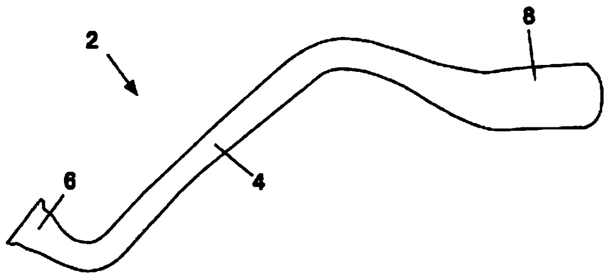
[0096] Figure 1A A filling tube 2 for a fuel tank (not shown) is shown. The filling tube 2 has a tube part 4 made of plastic. In the present invention, the pipe part 4 has been made of thermoplastic material. The tube part 4 can be made of plastic in a single layer. The tube part 4 can alternatively be made in multiple layers from a coextruded hose material which is molded in a blow mold by applying internal pressure. The tube part 4 can be molded to bend in at least two spatial directions by means of a blow molding process.

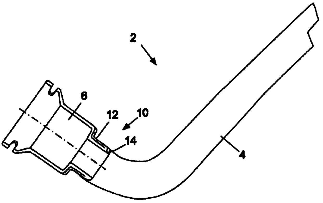
[0097] The filling tube 2 has a tubular adapter 6 which is connected to the tube part 4 . The adapter 6 is used to couple the filling pipe 2 to the fuel tank. At the end 8 of the filling tube 2 opposite the adapter 6 , the tube part 4 has an enlarged diameter, wherein said enlarged end 8 is assigned to the filling for supplying fuel in the motor vehicle in the fully assembled state. head.

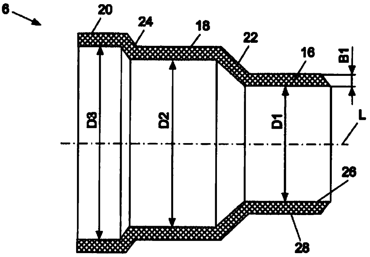
[0098] Figure 1B shown in longitudinal section Figure ...


PUM


Abstract

The invention relates to a filler tube for a fuel tank, having a tube portion (4) made of plastic material and a tubular adapter (6), which is connected to the tube portion (4), for coupling the filler tube (2) to the fuel tank, wherein a lateral surface (12, 28) of the adapter (6) is integrally bonded, in particular welded, to a lateral surface (14) of the tube portion (4), wherein the adapter (6) and the tube portion (4) overlap in the region of the integrally bonded connection.

Description

technical field [0001] The invention relates to a filling tube for a fuel tank with a tube part made of plastic and a tubular adapter connected to the tube part and used for coupling the filling tube to the fuel tank. The invention also relates to a tank system with a filling tube of the type described. Finally, the invention relates to a method and a device for producing a filling tube for a fuel tank. Background technique [0002] In the development of modern motor vehicles there is a constant need to further reduce pollutant emissions, firstly to meet increasingly stringent legal requirements and secondly to meet customer demands for extremely environmentally friendly vehicles. Of the utmost importance here are the reduction of vehicle weight and the reliable encapsulation of environmentally harmful substances, such as fuels or lubricants. [0003] In the context of these objectives, this means that, in order to develop a tank system consisting of a fuel container and a...

Claims


Application Information

Patent Timeline
IPC IPC(8): B29C49/20B60K15/04
CPCB60K2015/03467B29C49/20B60K2015/0346B60Y2410/122B60Y2410/124B29L2023/00B29L2023/22B29C49/04B29C2049/2047B29L2031/30B60K15/04B29L2031/7172B60K2015/0458
Inventor D·施米茨D·塞利格C·克吕格尔H·洛伦茨
Owner KAUTEX TEXTRON
Why Eureka
Try Eureka