Valve element assembling and locking equipment and using method thereof

A valve core and equipment technology, applied in metal processing equipment, using liquid/vacuum degree for liquid tightness measurement, by measuring the increase and deceleration rate of fluid, etc., can solve the one-way airtightness detection of automatic airtightness detection equipment, It cannot meet the high-precision detection requirements of faucets, does not have the air-tightness detection function, etc., so as to reduce the purchase amount of equipment, improve assembly efficiency and detection accuracy, and save manpower and material resources.

Active Publication Date: 2019-02-12
ZHEJIANG ORCHID IND CO LTD
View PDF6 Cites 2 Cited by
  • Summary
  • Abstract
  • Description
  • Claims
  • Application Information

AI Technical Summary

Problems solved by technology

However, the key to affecting the airtightness of the faucet is the assembly and locking of the valve core and the valve body. The inspection of the finished faucet cannot detect and eliminate the unqualified products in the assembly process of the valve core and the valve body in time, and the subsequent assembly process will cause various production capacity. The waste of resources increases the production cost; at present, the air tightness detection of faucets is usually carried out manually, and the test personnel need to constantly confirm various operating parameters, the detection efficiency is low, the labor cost is high, time-consuming and labor-intensive, and error-prone, the detection effect is unstable. Testing quality cannot be guaranteed
[0005] At present, there are also some automated faucet assembly equipment, but either do not have the airtightness detection function, or the airtightness detection process is separated from the assembly process of the valve core and the valve body, and multiple handling and disassembly operations are required in the middle, which leads to poor equipment structure. Complicated and cumbersome, time-consuming and error-prone, the detection efficiency is low; and the automatic air-tightness detection equipment usually can only perform one-way air-tightness detection, the detection effect is unstable, the quality cannot be guaranteed, and it cannot meet the high-precision detection requirements of faucets

Method used


Image

  • Valve element assembling and locking equipment and using method thereof
  • Valve element assembling and locking equipment and using method thereof
  • Valve element assembling and locking equipment and using method thereof

Examples


Embodiment Construction

[0041] In order to explain the overall concept of the present application more clearly, the following detailed description will be given by way of examples in combination with the accompanying drawings.

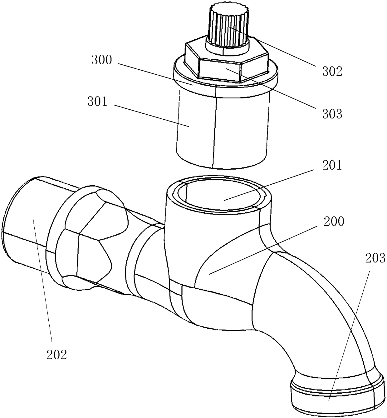
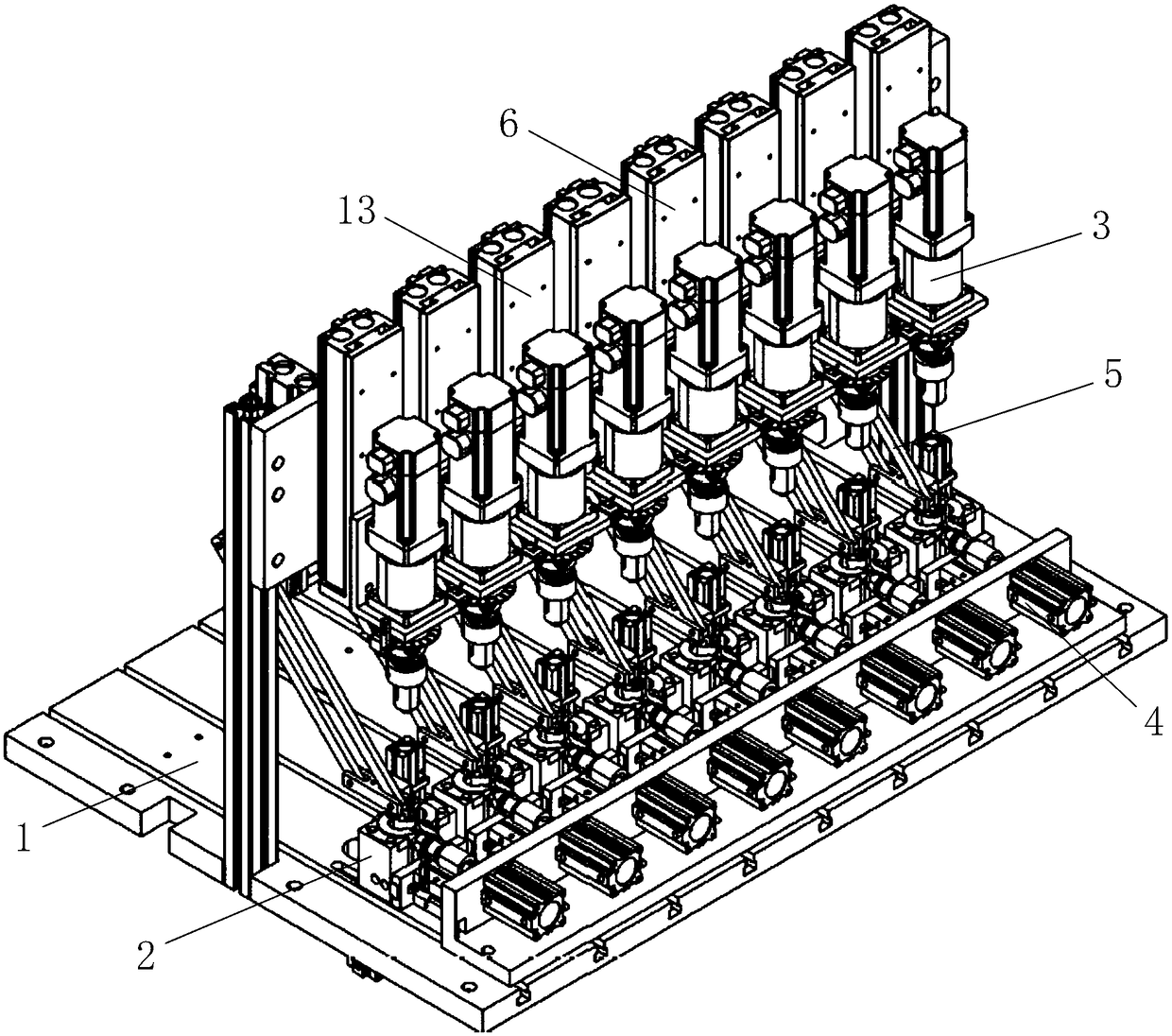
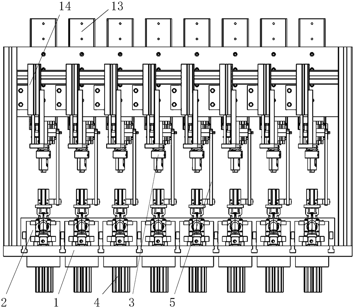
[0042] Such as figure 2 , image 3 and Figure 4 As shown, the embodiment of the present application proposes a valve core assembly and locking device, which includes a body 1 , a clamping and fixing unit 2 , a locking switch unit 3 and an airtight detection unit 4 arranged on the body 1 . Among them, the clamping and fixing unit 2 is used to accommodate and fix the valve body 200, prevent the valve body 200 from moving during the assembly process, and facilitate the locking switch unit 3 to lock the valve core 300 on the valve body 200 and facilitate airtight testing. The unit 4 is connected with the valve body 200 . The locking switch unit 3 can move relative to the clamping and fixing unit 2 to move to the valve body 200 and the valve core 300 in the clamping and fixin...


PUM


Abstract

The invention discloses valve element assembling and locking equipment and a using method thereof. The valve element assembling and locking equipment comprises a body and a clamping and fixing unit, alocking and opening and closing unit and an airtightness detection unit which are arranged on the body; the clamping and fixing unit is used for containing and fixing a valve body; the locking and opening and closing unit can move relative to the clamping and fixing unit and comprises a locking module and an opening and closing module, the locking module can lock a valve element on the valve body, and the opening and closing module can drive a valve rod of the valve element to move to open or close a combined body of the valve body and the valve element; and the airtightness detection unit can be connected with an inlet and an outlet of the valve body and can detect the airtightness of the combined body of the valve body and the valve element in a closed state and the airtightness and theventability of the combined body of the valve body and the valve element in an opened state. According to the valve element assembling and locking equipment and the using method thereof, the assemblyefficiency and the detection precision can be greatly improved, the product qualification rate is increased, the equipment occupation space is reduced, manpower and material resources are saved, theproduction and manufacture cost is reduced, and the valve element assembling and locking equipment is suitable for being applied and popularized on a large scale.

Description

technical field [0001] The application belongs to the technical field of water valve (faucet) assembly equipment, and in particular relates to a valve core assembly and locking equipment and a use method thereof. Background technique [0002] Water valve is commonly called as faucet, is used for controlling the size switch of water flow. Such as figure 1 As shown, a common faucet usually includes a valve body 200 and a valve core 300. The valve body 200 is provided with a valve core installation port 201, at least one inlet 202 and an outlet 203. The valve core 300 is installed on the valve body 200 through the valve core installation port 201. Inside, functions such as direction control, pressure control or flow control are realized by means of the switch of the spool 300; 302 is fixedly connected with the movable valve plate, and the movable valve plate is driven to move by moving the valve stem 302 to open or close the valve core 300; Part 301 is fixedly connected to l...

Claims


Application Information

Patent Timeline
Patent Type & Authority Applications(China)
IPC IPC(8): B23P19/04G01M3/28
Inventor 张松平曾志明
Owner ZHEJIANG ORCHID IND CO LTD
Why Eureka
Try Eureka