Connecting system between steel frame and prefabricated wall plate and manufacturing method

A prefabricated wall panel and connection system technology, applied to walls, building components, building insulation materials, etc., can solve the problems of prefabricated wall panels such as heavy weight and volume, difficult to guarantee construction quality, and no assembly construction, etc., to achieve simple production methods Convenience, improvement of waterproof and heat insulation performance, and weight reduction effect

Inactive Publication Date: 2019-02-12
HEFEI UNIV OF TECH
View PDF7 Cites 1 Cited by
  • Summary
  • Abstract
  • Description
  • Claims
  • Application Information

AI Technical Summary

Problems solved by technology

[0003] In the existing technology, prefabricated wallboards are cumbersome due to their heavy weight and large volume, and the construction process is relatively cumbers

Method used


Image

  • Connecting system between steel frame and prefabricated wall plate and manufacturing method
  • Connecting system between steel frame and prefabricated wall plate and manufacturing method
  • Connecting system between steel frame and prefabricated wall plate and manufacturing method

Examples


Embodiment 1

[0050] Such as Figure 1-8 As shown, a connection system between a steel frame and a prefabricated wall panel includes a steel frame 1, a prefabricated wall panel 2, and a connecting piece. In this embodiment, each component and the connection mode of each component in the system are described in detail.

[0051] steel frame 1

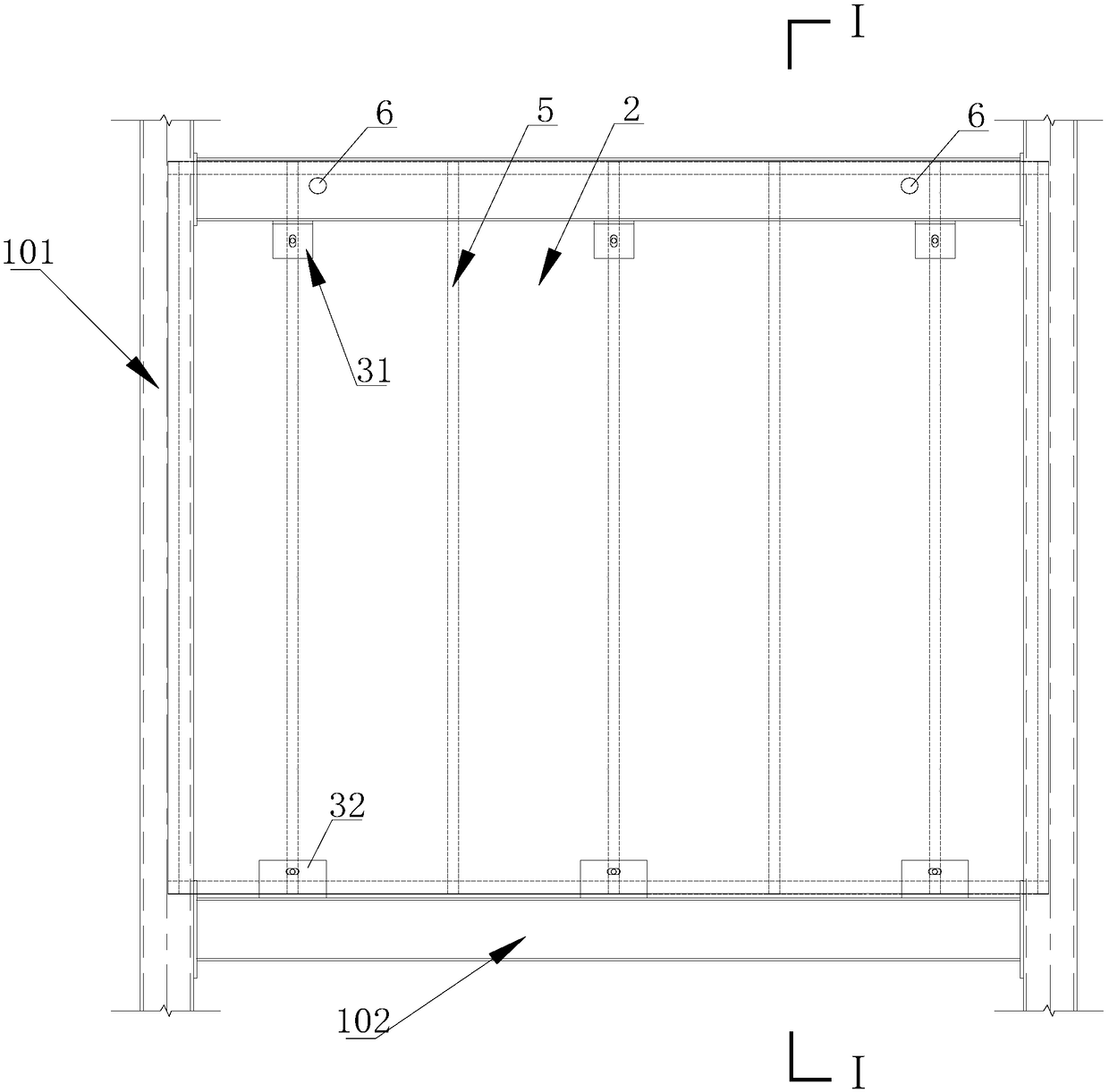
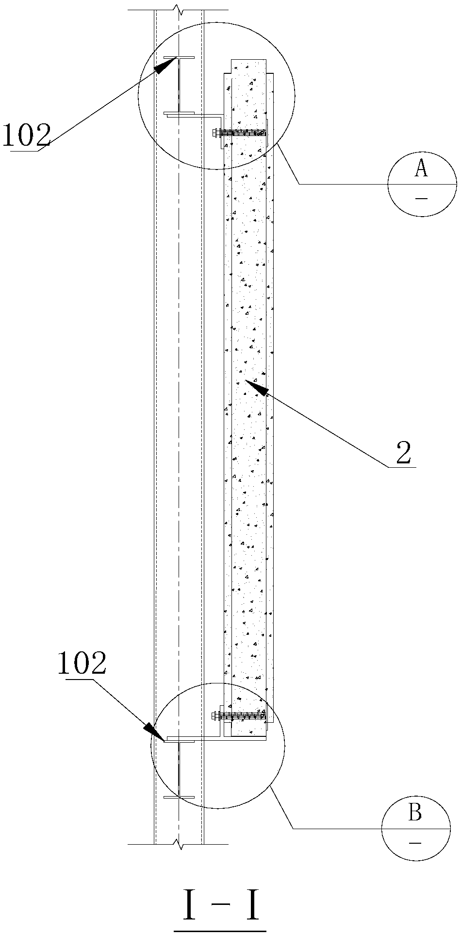
[0052] Such as Figure 5 As shown, the steel frame 1 includes two vertical steel columns 101 and two horizontal steel beams 102 , and the two horizontal steel beams 102 are vertically arranged between the two vertical steel columns 101 . The vertical steel column 101 is a square steel pipe column, the width and thickness of the column section are 400 mm and 14 mm, respectively, and the horizontal steel beam 102 is an H-shaped horizontal steel beam 102. The beam height, beam width, web thickness, and flange thickness are respectively 400mm, 200mm, 8mm, 13mm. Take two adjacent horizontal steel beams 102 as an example.

[0053] Precast wall panels 2 ...

Embodiment 2

[0072] The manufacturing method of the system connecting the steel frame 1 and the prefabricated wall panel 2 in embodiment 1 comprises the following steps:

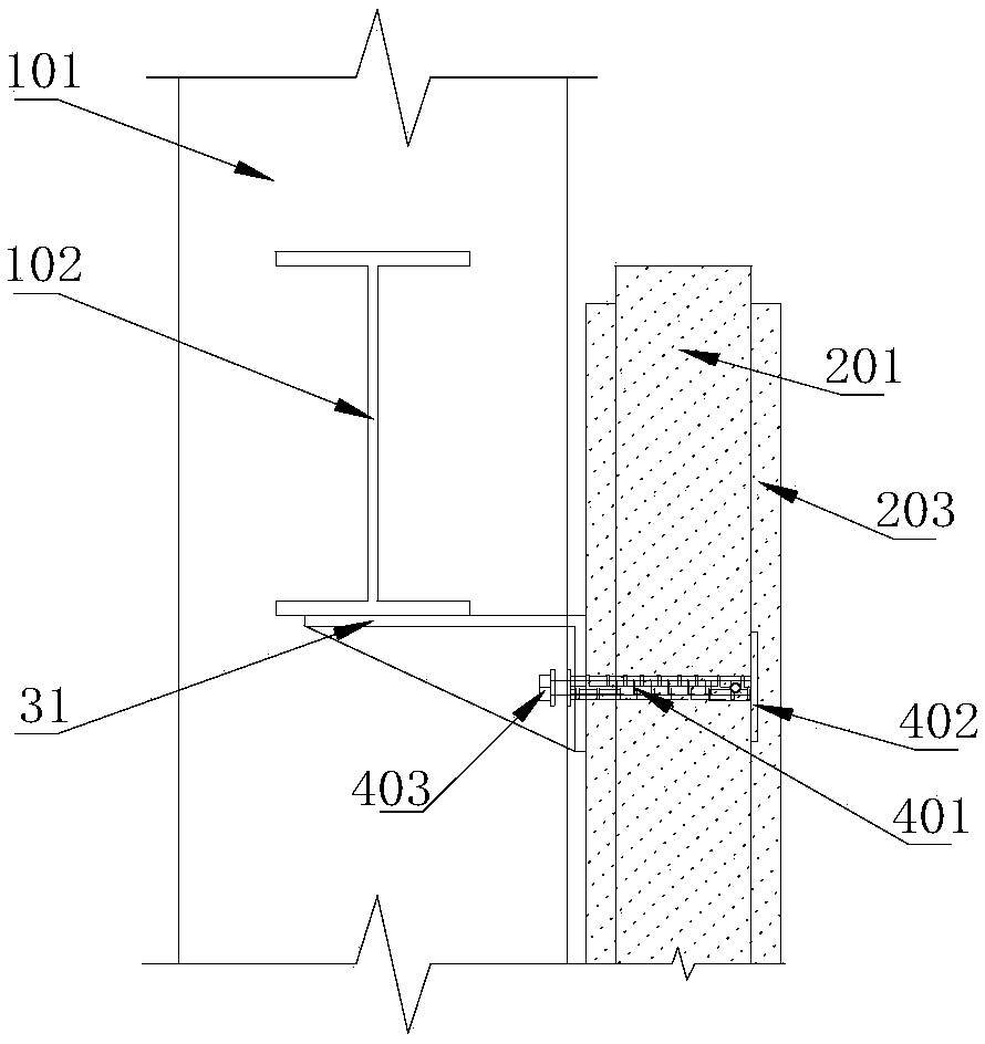
[0073] S1. Make C-shaped steel and open holes, assemble the C-shaped steel into the wall panel joist frame, set the keel reinforcement 204 on the corresponding position of the wall panel joist frame, and fix one end of the inner wire sleeve 401 with the anchor plate 402 to form a pre-embedded Part 4, the inner wire sleeve 401 passes through the hole in the corresponding position of the keel reinforcement 204 and the C-shaped steel 201, and the PVC pipe 6 is arranged inside the junction of the two C-shaped steels at the upper end of the wall panel keel, as a prefabricated wall. The hoisting hole of the panel 2 is placed in the mould, and the light polymer is poured to form the prefabricated wall panel 2; the horizontal steel beam 102 and the vertical steel column 101 are assembled to form the steel frame 1; the first conne...


PUM

PropertyMeasurementUnit
Densityaaaaaaaaaa

Abstract

The invention belongs to the field of construction engineering, and particularly relates to a connecting system between a steel frame and a prefabricated wall plate and a manufacturing method. The steel frame comprises longitudinal steel columns and horizontal steel beams. Each horizontal steel beams is vertically arranged between two longitudinal steel columns. The connecting system comprises first connecting pieces and second connecting pieces. The first connecting pieces are connected with the horizontal steel beam above and the upper part of the prefabricated wall plate. The second connecting pieces connected with the horizontal steel beam below and the lower part of the prefabricated wall plate. The prefabricated wall plate is arranged in an array mode in the hollow frame formed by the upper and lower horizontal steel beams and the adjacent longitudinal steel columns. The connecting system has the advantages that the horizontal steel beams are connected with the embedded pieces ofthe prefabricated wall plate by the connecting pieces, connection between the prefabricated wall plate and the steel frame is achieved, and the method is simple and convenient.

Description

technical field [0001] The invention relates to the field of construction engineering, in particular to a connection system and a manufacturing method of a steel frame and a prefabricated wall panel. Background technique [0002] In recent years, my country's prefabricated buildings have developed vigorously, especially prefabricated steel structure buildings, which have entered a new period of development. Prefabricated components are easy to produce and maintain, have high economic benefits, and have a wide range of applications, which is in line with the current development trend of my country's construction industrialization. The steel frame can well realize the prefabrication of the structure, and at the same time has the characteristics of large building space and flexible layout. [0003] In the prior art, prefabricated wallboards have a cumbersome construction process due to their heavy weight and large volume, and there is no real assembly construction, and at the ...

Claims


Application Information

Patent Timeline
IPC IPC(8): E04B2/82E04B1/68E04B2/76E04B2/78
CPCE04B1/68E04B2/76E04B2/789E04B2/82
Inventor 王静峰赵鹏汪皖黔潘广东
Owner HEFEI UNIV OF TECH
Why Eureka
Try Eureka