
Overwater floating heat-pipe-radiating thermoelectric power generating set

A technology of floating on water surface and thermoelectric power generation, applied in the direction of generators/motors, electrical components, etc., can solve problems such as restricting the application of thermoelectric power generation technology, affecting the efficiency of thermoelectric power generation devices, thermal expansion and contraction of thermoelectric power generation sheets, etc., to achieve excellent condensation effect Effect

Inactive Publication Date: 2019-02-12
CHONGQING THREE GORGES UNIV
View PDF4 Cites 3 Cited by
  • Summary
  • Abstract
  • Description
  • Claims
  • Application Information

AI Technical Summary

Problems solved by technology

As a result, the temperature of the heat-absorbing end is getting higher and higher, and the temperature of the heat-releasing end is also getting higher and higher, causing the thermoelectric power generation sheet to remain in a high temperature state, and the power generation efficiency is further reduced, thus restricting the application of thermoelectric power generation technology
At the same time, due to the relatively large change in temperature, the thermal expansion and contraction of the thermoelectric power generation sheet have caused higher requirements on the material strength and connection of the thermoelectric power generation sheet.
In the case that the material strength and connection of the thermoelectric power generation sheet cannot meet the requirements, it will affect the efficiency of the thermoelectric power generation device

Method used


Image

  • Overwater floating heat-pipe-radiating thermoelectric power generating set
  • Overwater floating heat-pipe-radiating thermoelectric power generating set
  • Overwater floating heat-pipe-radiating thermoelectric power generating set

Examples


Embodiment

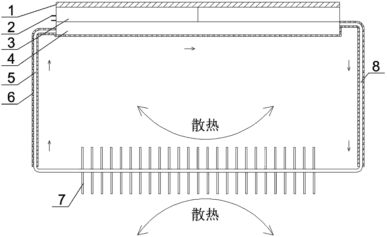
[0022] The embodiment of the present invention includes a solar heat absorbing plate 1, a thermoelectric power generation sheet group 3 and a loop heat pipe cooling system;

[0023] The solar heat absorbing plate 1 is arranged on the heat absorbing end of the thermoelectric power generation sheet group 3 through heat conducting glue, the solar heat absorbing plate 1 is made of copper or aluminum thin plate, and the upper surface of the solar heat absorbing plate 1 is coated with a photovoltaic plate to absorb heat Paint film.

[0024] The loop heat pipe cooling system includes an evaporator 4 and a condenser 7 , and the lower surface of the evaporator 4 is pasted with a rubber-plastic closed-cell insulation layer 6 .

[0025] The liquid inlet of the evaporator 4 is communicated with the liquid outlet of the condenser 7 through a liquid pipeline 5, and the outer wall of the liquid pipeline 5 is provided with an insulating buoyancy layer of rubber and plastic closed-cell materia...


PUM


Abstract

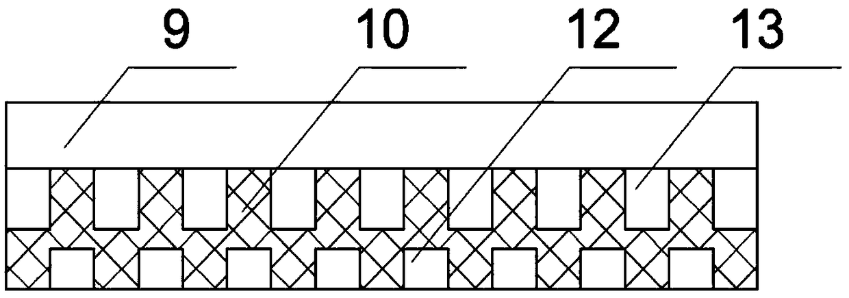
The invention discloses an overwater floating heat-pipe-radiating thermoelectric power generating set and relates to the field of thermoelectric power generating equipment. The overwater floating heat-pipe-radiating thermoelectric power generating set comprises a solar absorbing plate, a thermoelectric power generator unit and a loop heat pipe radiating system. The solar absorbing plate is arranged at the absorbing end of the thermoelectric power generator unit. The loop heat pipe radiating system comprises an evaporator and a condenser; a liquid inlet of the evaporator is communicated with anintake port of the condenser through a liquid line; the liquid inlet of the evaporator is provided with a compensator; an exhaust port of the evaporator is communicated with an intake port of the condenser via a gas line and is provided with a gas collection chamber; a capillary core is laid horizontally between the compensator and the gas collection chamber; a plurality of gas passages communicated with the gas collection chamber are arranged parallelly above the capillary core; a plurality of liquid passages communicated with the compensator are arranged below the capillary core; therefore,thermoelectric power generation efficiency can be improved, and the service life of the overwater floating heat-pipe-radiating thermoelectric power generating set can be extended.

Description

technical field [0001] The invention relates to a water-surface floating heat pipe cooling thermoelectric power generation device, and mainly relates to the field of thermoelectric power generation equipment. Background technique [0002] Since the thermoelectric power generation technology was proposed, the main reasons why it has not been widely promoted are: low power generation efficiency, poor high temperature resistance and other factors. In-depth analysis is not difficult to find that there is an intrinsic relationship between low power generation efficiency and poor high temperature resistance. The main reason for the low power generation efficiency is that the heat dissipation effect of the heat release end of the thermoelectric power generation sheet is poor, resulting in a sharp increase in temperature, which reduces the temperature difference required for thermoelectric power generation. Therefore, in order to ensure the efficiency of thermoelectric power genera...

Claims


Application Information

Patent Timeline
IPC IPC(8): H02N11/00
CPCH02N11/002
Inventor 陈才刘利利程龙飞郭远臣郭正超孙岩胡科
Owner CHONGQING THREE GORGES UNIV
Learn More