Gas generating device for agricultural greenhouse

A gas generating device and gas generating technology, applied in agriculture, application, climate change adaptation, etc., can solve the problems of lack of stirring function, slow reaction speed, slow speed, etc., to speed up the reaction speed and adequacy, and speed up the flow speed. , the effect of improving convenience

Inactive Publication Date: 2019-02-15
黄仙才
View PDF21 Cites 1 Cited by
  • Summary
  • Abstract
  • Description
  • Claims
  • Application Information

AI Technical Summary

Problems solved by technology

[0003] After retrieval, the Chinese patent number is CN 207626172 U, which discloses a carbon dioxide generator for agricultural greenhouses, including a reaction tank, an acid storage tank, and an alkali storage tank; the base is rectangular; the reaction tank is arranged on the upper part of the base, and The reaction tank and the base are connected by bolts; the acid storage tank is set on the right side of the reaction tank. The above-mentioned patents have the following deficiencies in the process of use: 1. It does not have the stirring function, and the carbonate raw material and the strong acid raw material are mixed During the reaction, the reaction speed is slow, and the production speed of carbon dioxide gas is slow. 2. When the carbonate raw material reacts with the strong acid raw material, heat will be released, and the temperature of the generated carbon dioxide gas will be high, and the hot gas will float up, which will not be conducive to the carbon dioxide gas. sinking and rapid diffusion

Method used


Image

  • Gas generating device for agricultural greenhouse
  • Gas generating device for agricultural greenhouse
  • Gas generating device for agricultural greenhouse

Examples


Embodiment Construction

[0028] The following will clearly and completely describe the technical solutions in the embodiments of the present invention with reference to the accompanying drawings in the embodiments of the present invention. Obviously, the described embodiments are only some, not all, embodiments of the present invention.

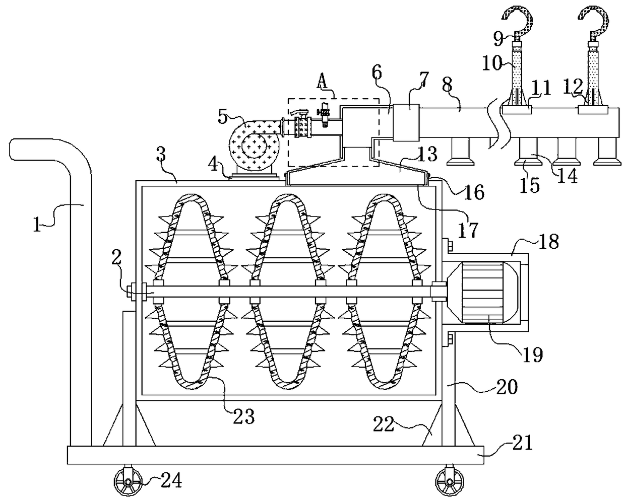
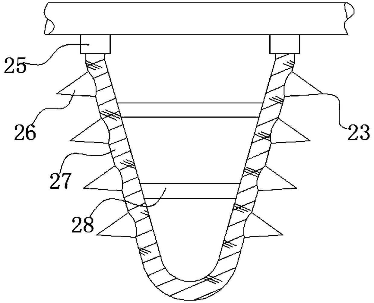
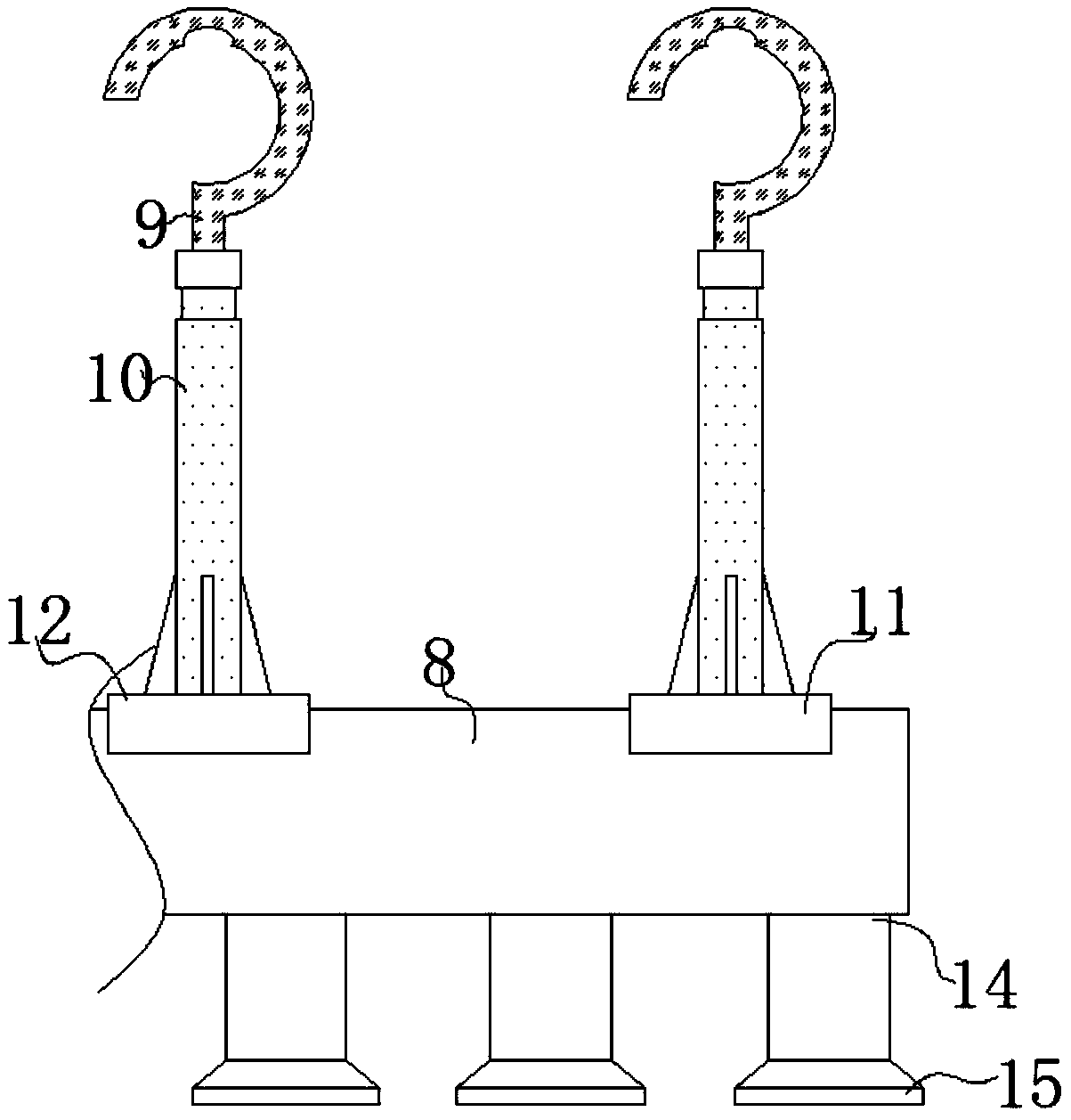
[0029] refer to Figure 1-5 , a gas generating device for agricultural greenhouses, comprising a bottom plate 21, a push handle 1 is welded on the top outer wall of the bottom plate 21, four rollers 24 are fixed on the bottom outer wall of the bottom plate 21 by bolts, and four support plates are welded on the top outer wall of the bottom plate 21 20, and the outer walls of the opposite side of the four support plates 20 are welded with a horizontally placed gas generating box 3, and the outer walls of both sides of the four support plates 20 near the bottom are welded with reinforcement plates 22, and the bottom outer walls of the reinforcement plates 22 are welded ...


PUM


Abstract

The invention discloses a gas generating device for an agricultural greenhouse. The gas generating device comprises a baseplate, a push handle is welded to the outer wall of the top of the baseplate,four rolling wheels are fixed to the outer wall of the bottom of the baseplate through bolts, four supporting plates are welded to the outer wall of the top of the baseplate, and a gas generating boxwhich is placed horizontally is welded to the outer walls of the opposite sides of the four supporting plates; reinforcing walls are welded to the outer walls of the two sides, close to the bottom, ofthe each supporting plate respectively, and the outer walls of the bottoms of the reinforcing plates are welded to the baseplate separately; a motor cover is fixed to the outer wall of one side of the gas generating box through bolts and located on the side away from the push handle, and a motor is fixed to the inner wall of the motor cover through bolts. According to the carbon dioxide gas generating device in the agricultural greenhouse, the gas diffusing speed of the device is relatively high, and gas is diffused uniformly. When vegetables need to be watered, the device can water the vegetables while supplying gas to the vegetables, so that the functional diversity and practicality of the device are improved.

Description

technical field [0001] The invention relates to the technical field of gas generators, in particular to a gas generator for agricultural greenhouses. Background technique [0002] Greenhouse is a device used to cultivate some off-season crops at low temperature. In order to provide more carbon dioxide gas for photosynthesis of crops, it is necessary to add a carbon dioxide gas generating device in the greenhouse. At present, the commonly used method is to use carbonic acid Carbon dioxide is produced when salt reacts with strong acid. [0003] After retrieval, the Chinese patent number is CN 207626172 U, which discloses a carbon dioxide generator for agricultural greenhouses, including a reaction tank, an acid storage tank, and an alkali storage tank; the base is rectangular; the reaction tank is arranged on the upper part of the base, and The reaction tank and the base are connected by bolts; the acid storage tank is set on the right side of the reaction tank. The above-men...

Claims


Application Information

Patent Timeline
IPC IPC(8): A01G7/02A01G9/24
CPCA01G7/02A01G9/24A01G9/247Y02A40/25
Inventor 黄仙才
Owner 黄仙才
Why Eureka
Try Eureka