
Auxiliary device for laser cutting concrete pavement

A concrete pavement, laser cutting technology, applied in laser welding equipment, metal processing equipment, welding equipment and other directions, can solve the problems of splashing, low construction efficiency, cumbersome construction process of rebuilding, etc., achieve high efficiency, avoid shock vibration and noise and dust The effect of pollution

Active Publication Date: 2019-02-15
HUAZHONG UNIV OF SCI & TECH
View PDF10 Cites 2 Cited by
  • Summary
  • Abstract
  • Description
  • Claims
  • Application Information

AI Technical Summary

Problems solved by technology

However, the reconstruction process of concrete pavement is very cumbersome, and the pavement needs to be crushed and then paved
[0003] At present, the commonly used tools for breaking concrete pavement include jackhammers, hydraulic breakers, and cement pavement crushers. Noise, and even accidents caused by splashing gravel, so it is not suitable for road construction in densely populated cities, especially near hospitals, schools and residential buildings. The noise generated by wind pick construction will greatly affect people's lives
And now, in order to improve the mechanical properties of concrete roads, steel mesh is often laid in cement concrete. Commonly used concrete breaking tools can only break concrete stones, and it is difficult to cut steel bars, so the construction efficiency is low.

Method used


Image

  • Auxiliary device for laser cutting concrete pavement
  • Auxiliary device for laser cutting concrete pavement
  • Auxiliary device for laser cutting concrete pavement

Examples


Embodiment Construction

[0026] In order to make the object, technical solution and advantages of the present invention clearer, the present invention will be further described in detail below in conjunction with the accompanying drawings and embodiments. It should be understood that the specific embodiments described here are only used to explain the present invention, not to limit the present invention. In addition, the technical features involved in the various embodiments of the present invention described below can be combined with each other as long as they do not constitute a conflict with each other.

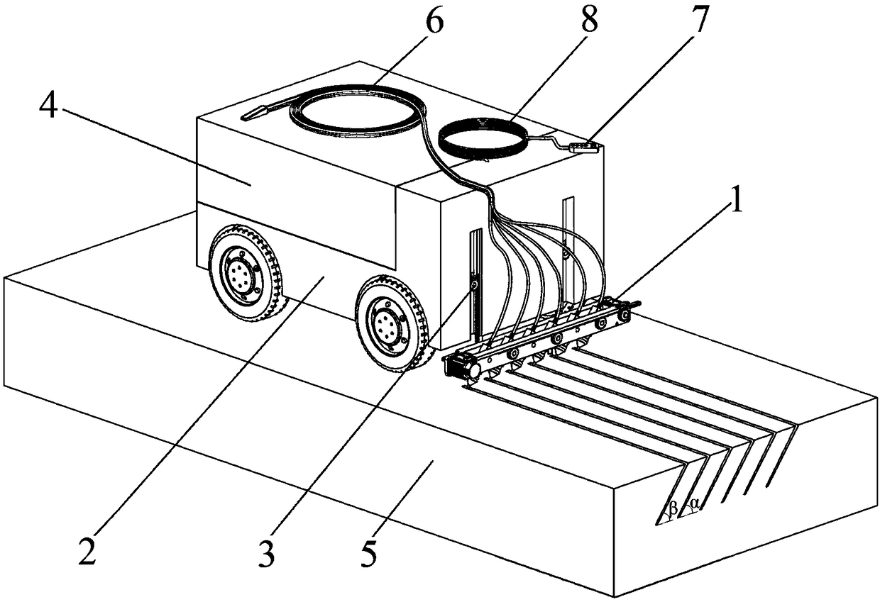
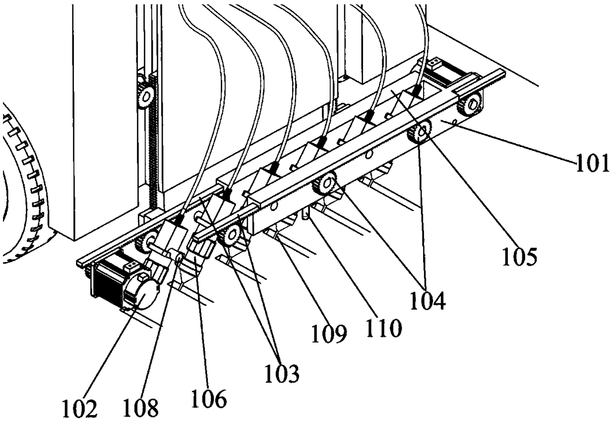
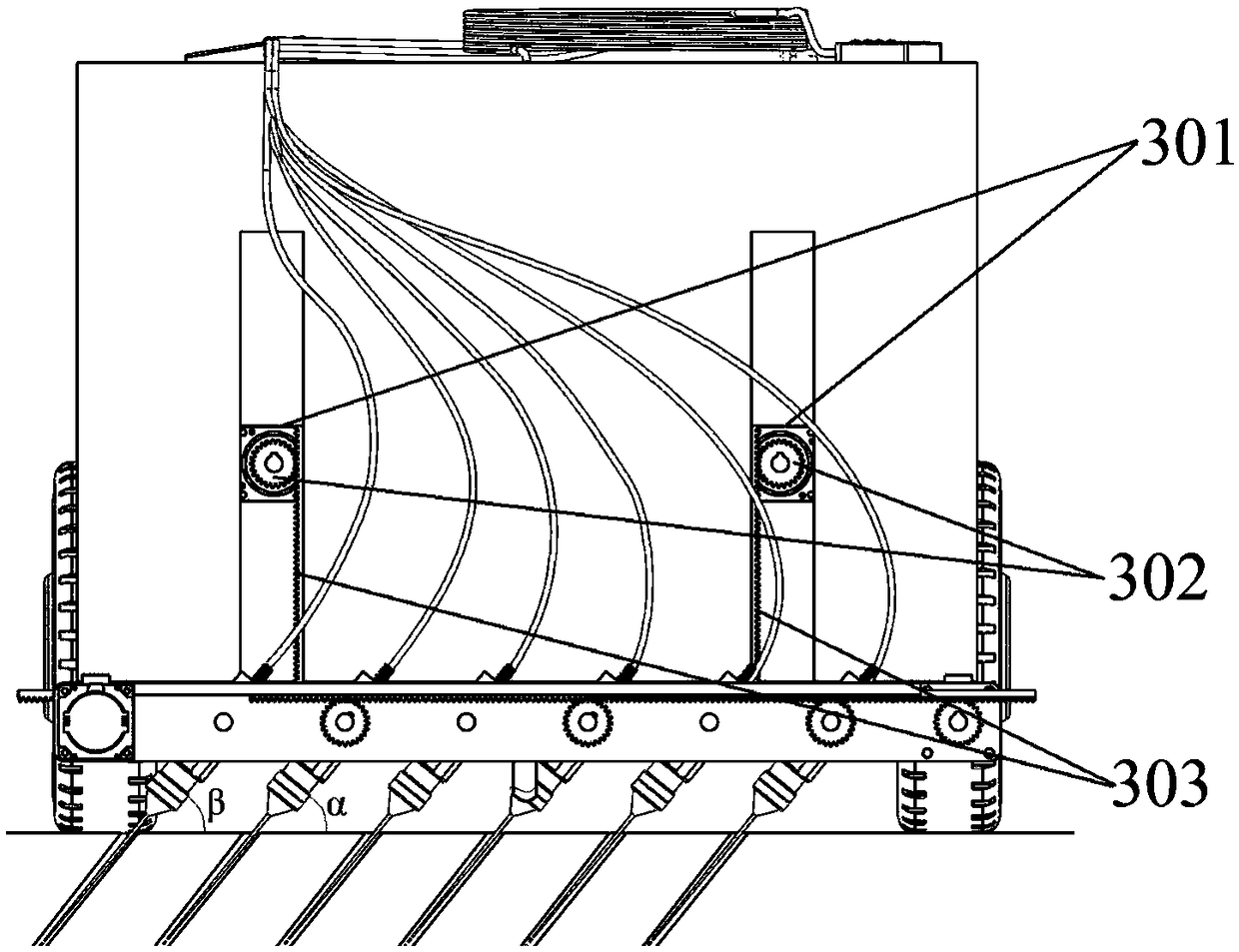
[0027] figure 1 It is an overall structural diagram of a laser cutting auxiliary breaking device for concrete pavement constructed according to a preferred embodiment of the present invention, as shown in figure 1 As shown, the device includes a cutting mechanism 1, a body 2, a lifting mechanism 3, a laser 4, a concrete pavement 5, an optical fiber armored cable 6, a control unit 7, a control c...


PUM


Abstract

The invention belongs to the field of road construction, and discloses an auxiliary device for laser cutting a concrete pavement. The device comprises a main body, a laser, a cutting mechanism, a lifting mechanism and an angle adjusting mechanism, The main body moves so as to change the cutting position; the cutting mechanism comprises multiple cutting heads arranged in parallel; each cutting headis used for emitting a laser light for cutting the concrete pavement; two groups of cutting heads are arranged; the cutting directions of the cutting heads in each group have the same direction; whenthe laser lights emitted by the two groups of cutting heads are intersected, a part to be cut is separated from an original concrete pavement, so that the concrete pavement is cut and crushed; the angle adjusting mechanism is used for adjusting the angle of each cutting head; and the lifting mechanism is used for adjusting the distance between the cutting mechanism and the ground. Through the auxiliary device for laser cutting the concrete pavement provided by the invention, the laser lights are adopted to cut and crush concrete in a non-contact way, so that the reinforced concrete pavement containing a reinforcing mesh is effectively cut, the cutting and crushing efficiency is high, and the impact vibration and the noise and dust pollution produced during the concrete pavement crushing process are effectively avoided.

Description

technical field [0001] The invention belongs to the field of road construction, and more specifically relates to an auxiliary device for laser cutting of concrete road surfaces. Background technique [0002] Concrete is widely used in the construction of houses, bridges, tunnels and roads because of its easy construction, high strength, long service life and strong ability to resist external forces. As a commonly used road structure type, cement concrete pavement has the advantages of high rigidity, strong bearing capacity, durability, high temperature resistance, high bending and tensile strength, and long fatigue life. It is widely used in national highways, provincial highways, Airports, factories, mines, roads, etc. However, the reconstruction process of concrete pavement is very cumbersome, and the pavement needs to be crushed and then paved. [0003] At present, the commonly used tools for breaking concrete pavement include jackhammers, hydraulic breaking hammers, an...

Claims


Application Information

Patent Timeline
Patent Type & Authority Applications(China)
IPC IPC(8): B23K26/36B23K26/38B23K26/402
CPCB23K26/36B23K26/38B23K26/402
Inventor 马修泉周邵巍邵新宇吴寒余希海曾鑫李正
Owner HUAZHONG UNIV OF SCI & TECH
Learn More