Unmanned aerial vehicle landing gear

A technology of unmanned aerial vehicles and landing gear, which is applied in the field of unmanned aerial vehicles, can solve the problems of not having ground friction and direction adjustment, damage of lifting inertial landing gear, and lack of electromagnetic fixing functions, etc., so as to achieve simple and fast power supply and increase use The effect of life and increasing the stability of use

Inactive Publication Date: 2019-02-15
YANTAI ANTELOPE NETWORK TECH CO LTD
View PDF0 Cites 2 Cited by
  • Summary
  • Abstract
  • Description
  • Claims
  • Application Information

AI Technical Summary

Problems solved by technology

[0003] With the development of society, UAVs are more and more widely used in people's lives. UAVs mainly include aircraft body, flight control system, data link system, launch recovery system, power supply system, etc. The flight control system is also called flight control system. The management and control system is equivalent to the "heart" part of the UAV system. It has an important impact on the stability of the UAV, the reliability, accuracy, and real-time performance of data transmission, and plays a decisive role in its flight performance. ;The data link system can ensure the accurate transmission of remote control instructions, as well as the real-time and reliability of the UAV receiving and sending information, so as to ensure the timely effectiveness of information feedback and the smooth and accurate completion of tasks. The drone is successfully lifted into the air to reach a safe height and speed, and safely falls back to the ground from the sky after completing the mission. The landing gear of the drone is the structure used for the landing support of the drone, usually on the supporting feet of the landing gear Rubber pads are set at the position, which can play a role of damping between the ground and the ground during take-off or landing. The existing landing gear does not have the ability to prevent ground friction and direction adjustment, and the landing gear is seriously damaged due to the lifting inertia, and does not have electromagnetic fixation. Function, can not meet people's needs, is not conducive to people's use

Method used


Image

  • Unmanned aerial vehicle landing gear
  • Unmanned aerial vehicle landing gear
  • Unmanned aerial vehicle landing gear

Examples


Embodiment 1

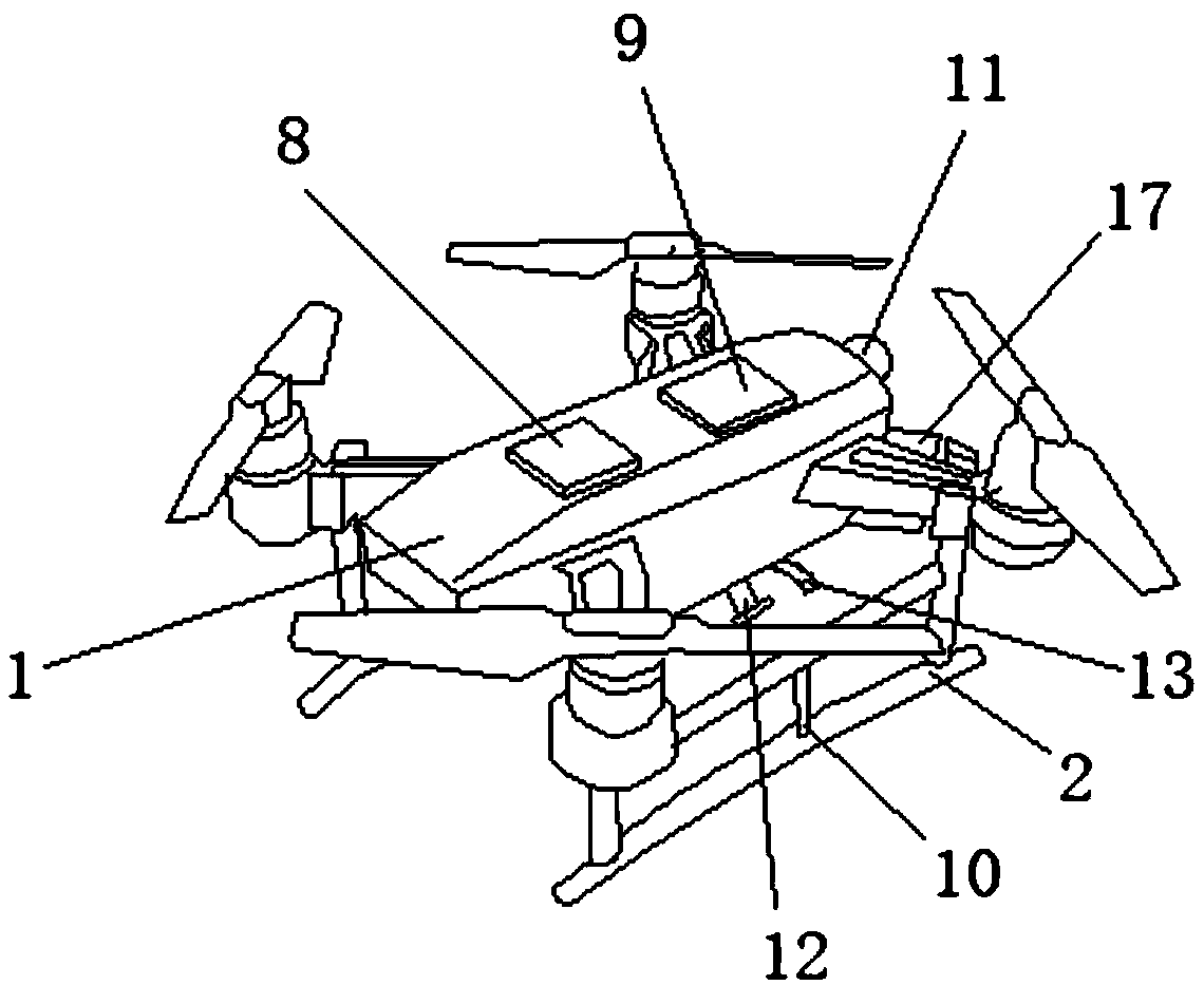
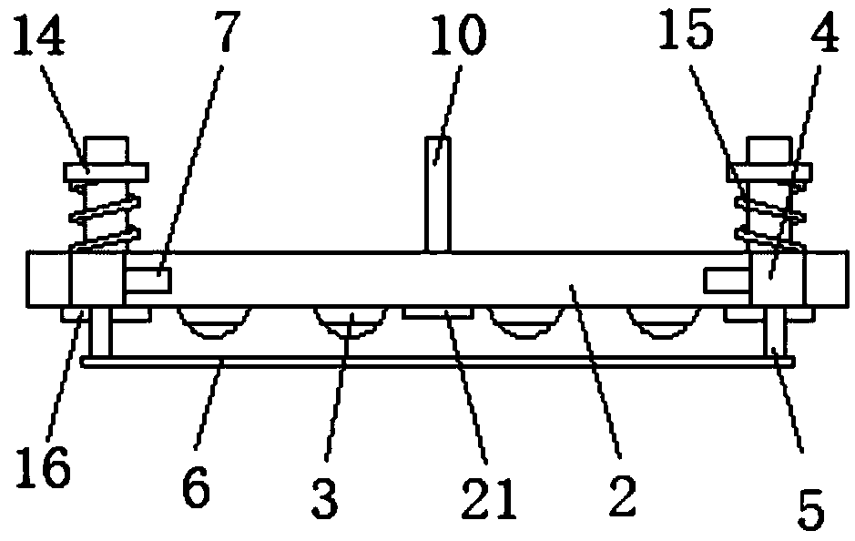
[0023] The landing gear of the UAV includes the UAV body 1, the bottom of the UAV body 1 is fixedly connected with a fixed rod 10, the inside of the landing gear 2 is provided with a chute 22, and the bottom end of the fixed rod 10 runs through the chute 22 and extends To the outside of the chute 22, the internal thread of the fixed rod 10 is connected with a bolt 21, and the bottom end of the bolt 21 passes through the fixed rod 10 and the chute 22 in turn and extends to the outside of the chute 22. By setting the fixed rod 10, the chute 22 And the bolt 21, when the drone lands, can reduce the impact force between the ground and the drone, and increase the service life of the drone. The surface of the leg of the drone body 1 is movably connected with the landing gear 2, The interior of the landing gear 2 is movably connected with universal balls 3, and the bottom of the universal balls 3 runs through the landing gear 2 and extends to the outside of the landing gear 2. Both sid...

Embodiment 2

[0025] The landing gear of the UAV includes the UAV body 1, the bottom of the 1 leg of the UAV body is fixedly connected with a connecting plate 16, and the top of the connecting plate 16 is movably connected with the bottom of the landing gear 2. By setting the connecting plate 16, the The landing gear 2 moves more stably, and the top and the bottom of the right side of the drone body 1 are fixedly connected with a signal lamp 11 and an illumination lamp 17 respectively. It is safer to use the drone at night. By setting the illumination lamp 17, the drone is convenient to use at night. The two sides of the bottom of the drone body 1 are respectively fixedly connected with the camera 12 and the baffle plate 13 located on the right side of the camera 12. The camera 12 The input terminal is electrically connected to the main board 9. By setting the camera 12, the drone has the functions of taking pictures and taking pictures. By setting the baffle 13, the camera 12 can be protect...

Embodiment 3

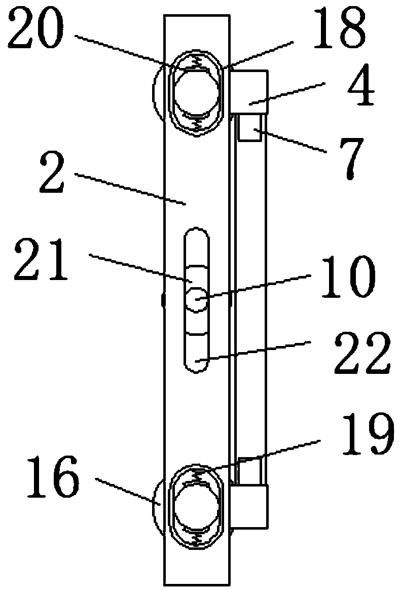
[0027]The landing gear of the UAV includes the UAV body 1, the bottom of the 1 leg of the UAV body is fixedly connected with a connecting plate 16, and the top of the connecting plate 16 is movably connected with the bottom of the landing gear 2. By setting the connecting plate 16, the The landing gear 2 moves more stably, and the surface of the UAV body 1 leg is movably connected with the landing gear 2, and the inside of the landing gear 2 is fixedly connected with a collar 18, and the inside of the collar 18 is fixedly connected with a compression spring 19, and the compression spring 19 One side of the rubber ring 20 is fixedly connected, and the inside of the rubber ring 20 is flexibly connected with the surface of the fixed rod 10. By setting the collar 18, the compression spring 19 and the rubber ring 20, the gap between the landing gear 2 and the fixed rod 10 can be reduced. impact force, increase the service life of the landing gear 2, the interior of the landing gear ...


PUM


Abstract

The invention discloses an unmanned aerial vehicle landing gear. The unmanned aerial vehicle landing gear comprises an unmanned aerial vehicle body; landing gears are movably connected to the surfacesof outriggers of the unmanned aerial vehicle body; universal balls are movably connected to the interiors of the landing gears; the bottoms of the universal balls penetrate through the landing gearsand extend out of the landing gears; and fixing blocks are fixedly connected to the two sides of the surfaces of the landing gears. According to the unmanned aerial vehicle landing gear, through coordinated use of the landing gears, the universal balls, the fixing blocks, telescopic guide columns, a magnetic pad, micro steering engines, a storage battery and a main board, the unmanned aerial vehicle landing gear can slide on the ground through the universal balls to prevent friction; and moreover, by fixing a liftable take-off and landing fixing device on a metal take-off and landing surface by using an electromagnetic mode, the adjusting and fixing of an unmanned aerial vehicle are effectively realized; the integral structure of the unmanned aerial vehicle landing gear is simple; the wearof the unmanned aerial vehicle landing gear is effectively reduced; the fixing of the unmanned aerial vehicle on the metal surface during taking-off and landing is realized; the power supply is simple and fast; the unmanned aerial vehicle landing gear can be repeatedly used and is good for people to use.

Description

technical field [0001] The invention relates to the technical field of unmanned aerial vehicle, in particular to the landing gear of unmanned aerial vehicle. Background technique [0002] Unmanned aircraft is referred to as "unmanned aerial vehicle", and the English abbreviation is "UAV". Compared with manned aircraft, drones are often more suitable for tasks that are too "dumb, dirty or dangerous". According to the application field, drones can be divided into military and civilian. In terms of military use, drones are divided into reconnaissance aircraft And target drones, civilian use, drones + industry applications, are the real rigid needs of drones; currently in aerial photography, agriculture, plant protection, micro selfies, express transportation, disaster relief, observing wild animals, monitoring infectious diseases, surveying and mapping, news Applications in fields such as reporting, power inspections, disaster relief, film and television shooting, and romance ...

Claims


Application Information

Patent Timeline
Patent Type & Authority Applications(China)
IPC IPC(8): B64C25/08B64C25/32B64C25/62B64D47/04B64D47/06B64D47/08
CPCB64C25/08B64C25/32B64C25/62B64D47/04B64D47/06B64D47/08B64C2025/325B64U2101/30B64U10/10
Inventor 谭朝予张传军
Owner YANTAI ANTELOPE NETWORK TECH CO LTD
Why Eureka
Try Eureka