Dual Rotor Duct System

A rotor duct and rotor technology, applied in the field of ducted rotor drones, can solve the problems of poor aerodynamic layout structure of the dual rotor duct system, increased wall loss, eddy current loss, and great influence of the ducted fan mechanism. , to achieve the effect of optimizing the layout of the transmission mechanism, reducing axial air leakage, and avoiding wall loss

Active Publication Date: 2021-11-30
SICHUAN UNIV
View PDF9 Cites 0 Cited by
  • Summary
  • Abstract
  • Description
  • Claims
  • Application Information

AI Technical Summary

Problems solved by technology

At present, the dual-rotor duct system has the following two main disadvantages. One is that its power motor is placed between the first rotor mechanism and the second rotor mechanism, which makes the turbulence inside the duct more serious and the aerodynamic resistance is greater; There is a certain gap between the tip of the first rotor and the second rotor and the inner wall of the duct, which has a great impact on the ducted fan mechanism. There is a large pressure difference on both sides of the gap between the tip of the rotor and the inner wall of the duct, causing Axial air leakage, the work formed by this part of the airflow is wasted, resulting in leakage loss. At the same time, the wingtip turbulence will also increase the wall loss and eddy current loss inside the duct, resulting in an increase in internal flow loss.
The above two shortcomings lead to poor aerodynamic layout structure of the dual-rotor duct system, which affects the control of the UAV, and the use effect is poor

Method used


Image

  • Dual Rotor Duct System
  • Dual Rotor Duct System

Examples


Embodiment Construction

[0022] The present invention will be further described below in conjunction with accompanying drawing.

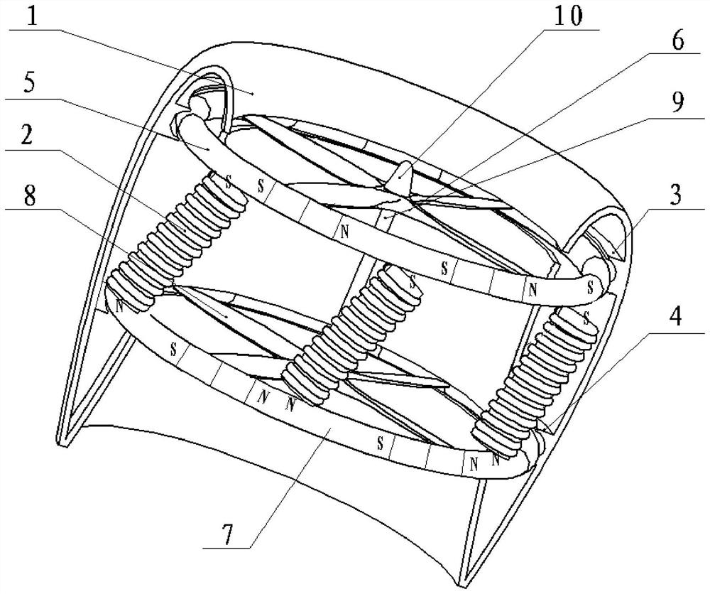
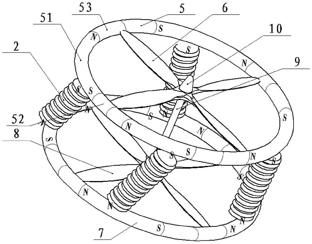
[0023] Such as figure 1 , figure 2 As shown, the dual-rotor duct system of the present invention includes a first rotor mechanism, a second rotor mechanism, a duct 1, and a plurality of electromagnetic coils 2, and the electromagnetic coil 2 controls the strength and weakness of its magnetic induction lines through the magnitude and direction of the current. periodic changes in direction;

[0024] The duct 1 is a hollow ring structure. The duct 1 includes an inner wall and an outer wall. The inner wall is provided with a first annular seam and a second annular seam. The first circular guide rail 3 and the second circular guide rail 4 are arranged in the interior, the first circular guide rail 3 and the second circular guide rail 4 have the same structure, and the first circular guide rail 3 and the second circular guide rail 4 are parallel to each other Setting, the fir...


PUM


Abstract

The disclosure of the present invention relates to the technical field of ducted rotor drones, in particular to a dual rotor ducted system, which includes a first rotor mechanism, a second rotor mechanism, a duct, and multiple electromagnetic coils. Inside the track, the first rotor mechanism includes a first rigid permanent magnet coil and a first rotor, and the second rotor mechanism includes a second rigid permanent magnet coil and a second rotor. After the electromagnetic coil is connected to an alternating current, the electromagnetic coil generates a coupled magnetic field. Under the action of the magnetic field, the first rotor mechanism rotates on the first circular guide rail, and the second rotor mechanism rotates on the second circular guide rail, and the first rotor mechanism and the second rotor mechanism rotate in opposite directions, while the first rotor mechanism It is connected with the second rotor through the connecting shaft, so that the first rotor and the second rotor can reverse at the same speed around the connecting shaft, which can effectively eliminate the torque of the first rotor and the second rotor, and it is more convenient to realize the control of the UAV. Posture control improves the use effect.

Description

technical field [0001] The invention relates to the technical field of ducted rotor UAVs, in particular to a dual-rotor ducted system. Background technique [0002] The ducted rotor drone is a device with a high lift-to-drag ratio. The built-in blade structure is used as the rotor structure to protect the rotor mechanism from the impact of external objects or airflow impacts, improving the safety and resistance of the drone. Interference ability. The power supply mechanism of the ducted rotor UAV is a rotor structure, and the rotor structure is mostly a double rotor. The double rotor structure is set inside the duct, and the double rotors are set parallel to each other, which can realize vertical take-off and landing and hovering, offsetting each other. The torque action does not require a special take-off and landing site, and it is also convenient to realize the control of the UAV's aerial attitude. At present, the dual-rotor duct system has the following two main disadv...

Claims


Application Information

Patent Timeline
Patent Type & Authority Patents(China)
IPC IPC(8): B64C27/20B64C27/10
CPCB64C27/10B64C27/20
Inventor 周青华贺小飞周博黄彦彦王鑫陈盛文杨勇
Owner SICHUAN UNIV
Why Eureka
Try Eureka