A hoisting method for boiler rear roof superheater components

A hoisting method and superheater technology, which is applied in the direction of transportation and packaging, load hanging components, etc., can solve the problems of long construction period and high installation cost, and achieve the effects of shortened construction period, fast assembly speed and high installation efficiency

Active Publication Date: 2019-12-17
中国能源建设集团江苏省电力建设第三工程有限公司
View PDF6 Cites 0 Cited by
  • Summary
  • Abstract
  • Description
  • Claims
  • Application Information

AI Technical Summary

Problems solved by technology

[0002] The rear top superheater of the power plant boiler is arranged on the top of the rear smoke shaft, the front is connected to the outlet header of the top superheater, the rear is connected to the rear wall, and the vertical section low-temperature reheater (referred to as vertical low reheater) and the upper section partition are interspersed in sequence in the middle. Wall superheater, vertical section low-temperature superheater (referred to as vertical low superheater), suspension pipe and other equipment. At present, the method of installing these parts of equipment in domestic thermal power unit boilers is to install first and then the top superheater, and start after all the installations are completed. Install the superheater and suspension pipes of the vertical lower section, the vertical lower section, the middle partition wall in the upper section one by one. The disadvantage of this construction method is that the construction period is long and the installation cost is high.

Method used


Image

  • A hoisting method for boiler rear roof superheater components
  • A hoisting method for boiler rear roof superheater components
  • A hoisting method for boiler rear roof superheater components

Examples


Embodiment 2

[0066] The boiler of the 2×350MW unit in this example is a supercritical parameter variable pressure operation once-through furnace produced by Shanghai Boiler (Group) Co., Ltd., single furnace, primary reheat, balanced ventilation, open air layout, solid slag discharge, all-steel frame, full suspension Hanging structure Π type boiler. The boiler superheated steam flow rate is 1172t / h, the superheated steam outlet pressure is 25.4MPa, the superheated steam outlet temperature is 571℃; the reheated steam flow rate is 962t / h, the reheated steam inlet and outlet pressure is 5.4 / 5.22MPa, and the reheated steam inlet and outlet temperature is 343 / 569. ℃; The design thermal efficiency is 93.9%.

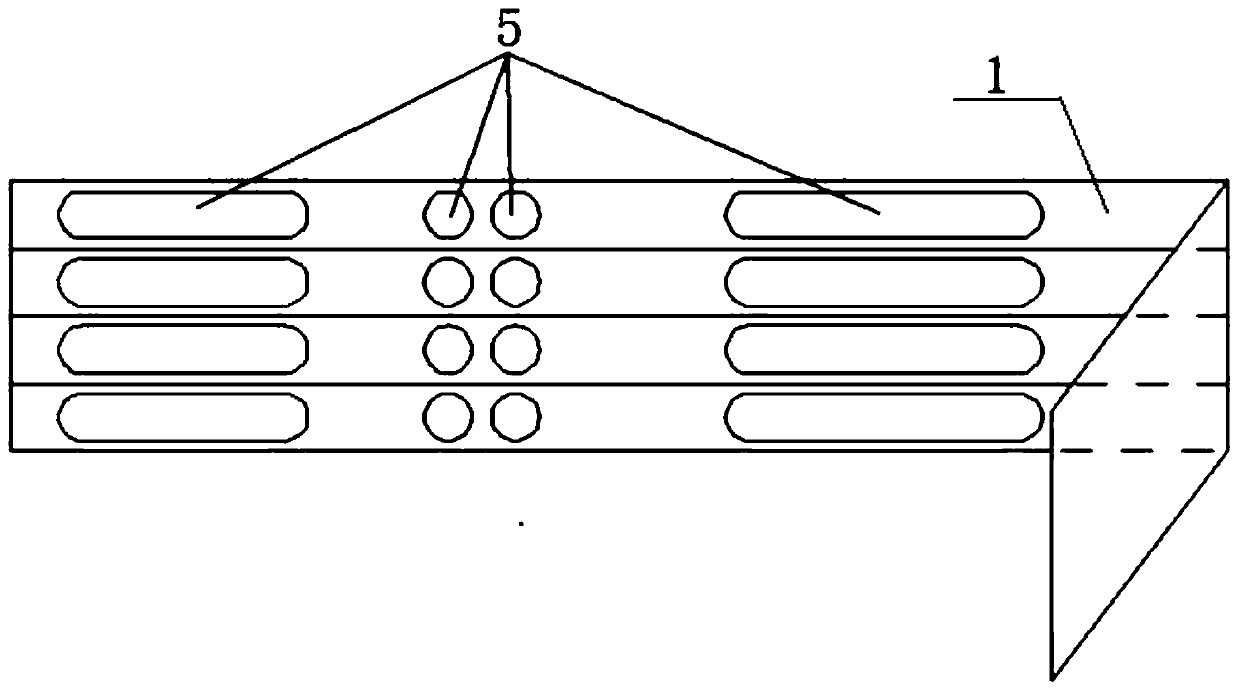
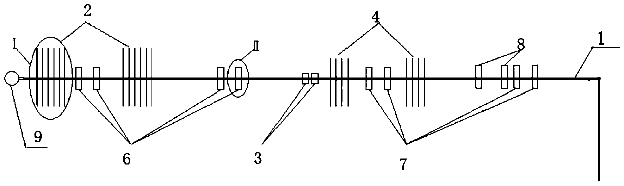
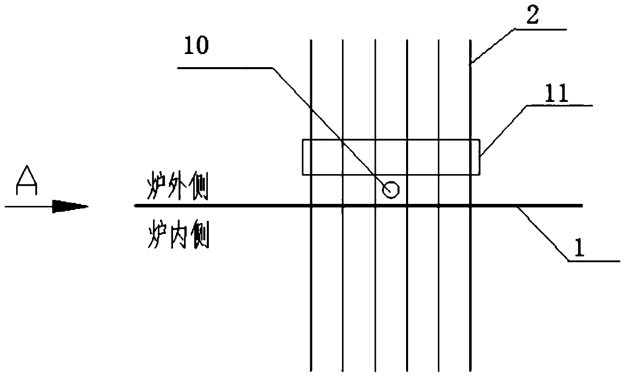
[0067] The boiler superheating system is divided into front top superheater, rear top superheater, wall superheater, low temperature superheater, panel superheater, final stage superheater, and the rear top superheater is arranged on the top of the flue gas area of ​​the back smoke well , Nume...


PUM


Abstract

The invention provides a hoisting method of a rear boiler roof superheater assembly of a boiler. The hoisting method comprises the following steps: ground assembling is conducted, specifically, a rearboiler roof superheater tube panel is erected on the ground, a vertical low-temperature reheater, an upper-section mid-partition superheater, a vertical low-temperature superheater and a suspension tube are mounted in wall penetrating holes of the rear boiler roof superheater tube panel in a penetrating mode through a crawler crane, and the other ends of the vertical low-temperature reheater, theupper-section mid-partition superheater, the vertical low-temperature superheater and the suspension tube are supported through a support; the assembly is overturned and hoisted, specifically, the assembled assembly is hoisted through the crawler crane and a horizontal tower crane to be overturned to be in a vertical state; and the assembly is hoisted in place, specifically, after being overturned, the assembly is hoisted in place through the horizontal tower crane, after being in place, the assembly is thrown to be hung on a boiler top plate secondary beam through a chain block, and after adjusting is completed, the assembled assembly is mounted. The hoisting method shortens the construction period greatly, a large part of a working face is completed on the ground, aloft work is reduced,safety is higher, and meanwhile, the cost of a main lifting appliance is reduced greatly.

Description

Technical field [0001] The invention belongs to the field of boiler construction and installation research, and in particular relates to a method for hoisting a superheater component of a boiler rear top. Background technique [0002] The back top superheater of the power plant boiler is arranged on the top of the back smoke shaft, the front is connected to the top superheater outlet header, the back is connected to the back wall, and the vertical section low temperature reheater (referred to as the vertical low reheater) and the upper partition are interspersed in turn. Wall superheater, vertical section low-temperature superheater (abbreviated as vertical low-pass), suspension pipe and other equipment. At present, the method of installing these parts of equipment in domestic thermal power unit boilers is to install the top superheater first, and start after all installations are completed The shortcomings of this construction method are the long construction period and the high...

Claims


Application Information

Patent Timeline
Patent Type & Authority Patents(China)
IPC IPC(8): B66C13/08
CPCB66C13/08
Inventor 吴忠民余兴
Owner 中国能源建设集团江苏省电力建设第三工程有限公司
Why Eureka
Try Eureka