Road rainwater pneumatic shunting treatment system and control method thereof
A technology for treating system and rainwater, which is applied in the fields of civil buildings and municipal water supply and drainage, and can solve the problems of high cost of electronic control and hydraulic control
- Summary
- Abstract
- Description
- Claims
- Application Information
AI Technical Summary
Problems solved by technology
Method used
Image

Examples
Embodiment 1
[0080] see figure 1 , figure 2 , image 3 , Figure 4 , Figure 5 As shown, the road rainwater pneumatic diversion treatment system is used to divert the fluid in the road municipal rainwater pipe 2, including:
[0081] Compressed gas source 10, used to provide compressed gas;
[0082] Gas delivery pipe, the gas delivery pipeline is used to deliver gas;
[0083] The diversion well 40 is arranged on the municipal rainwater pipe 2. The diversion well 40 includes a well body structure 41 and at least an inlet 42 arranged on the well body structure 41, a first water outlet pipe 43, a second water outlet pipe 44, and a third water outlet pipe 45 And the pneumatic cut-off device that is arranged on the second water outlet pipe 44, the third water outlet pipe 45 is respectively the second pneumatic cut-off device 46 and the third pneumatic cut-off device 47, wherein the inlet 42 communicates with the municipal rainwater pipe 2 upstream of the shunt well 40, the first A water out...
Embodiment 2
[0090] see Figure 6 As shown, on the basis of Embodiment 1: the system also includes a measuring instrument 60 and a controller 50, the measuring instrument 60 and the control valve 20 are electrically connected to the controller 50 respectively, and the controller 50 controls the control according to the measurement signal measured by the measuring instrument Valve 20 operates, wherein,
[0091] When the diversion well 40 is provided with the second pneumatic shut-off device 46 and the third pneumatic shut-off device 47, it is the first form:
[0092] The measuring instrument 60 is used to control the actions of the second control valve 22 and the third control valve 23 respectively, so that the second pneumatic shut-off device 46 deflates the second water outlet pipe 44, and the third pneumatic shut-off device 47 inflates the third water outlet pipe 45 to cut off , the domestic sewage that enters the diversion well 40 is diverted to the municipal sewage pipe 3 or the sewag...
Embodiment 3
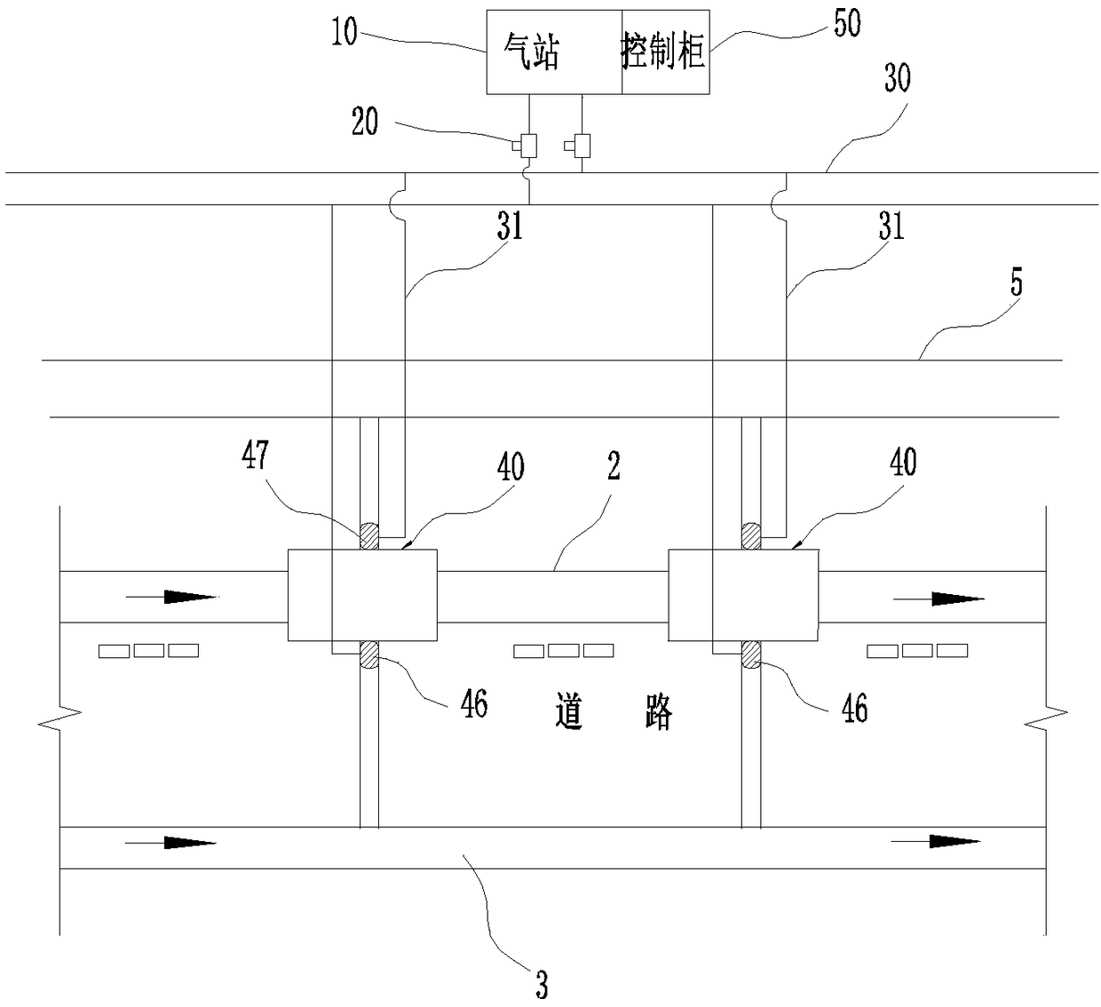
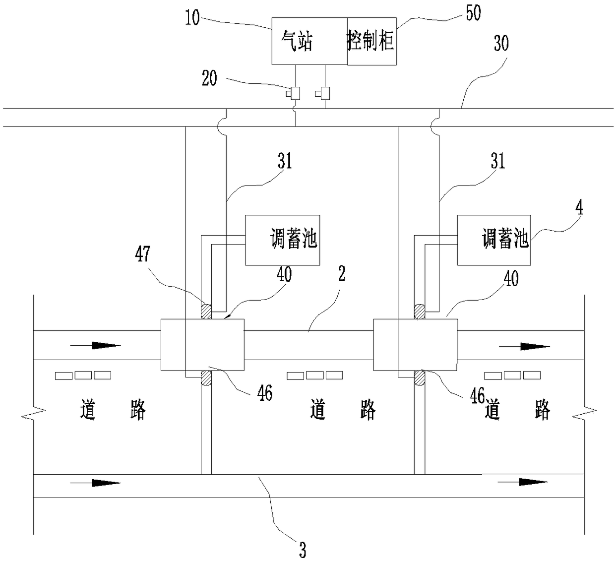
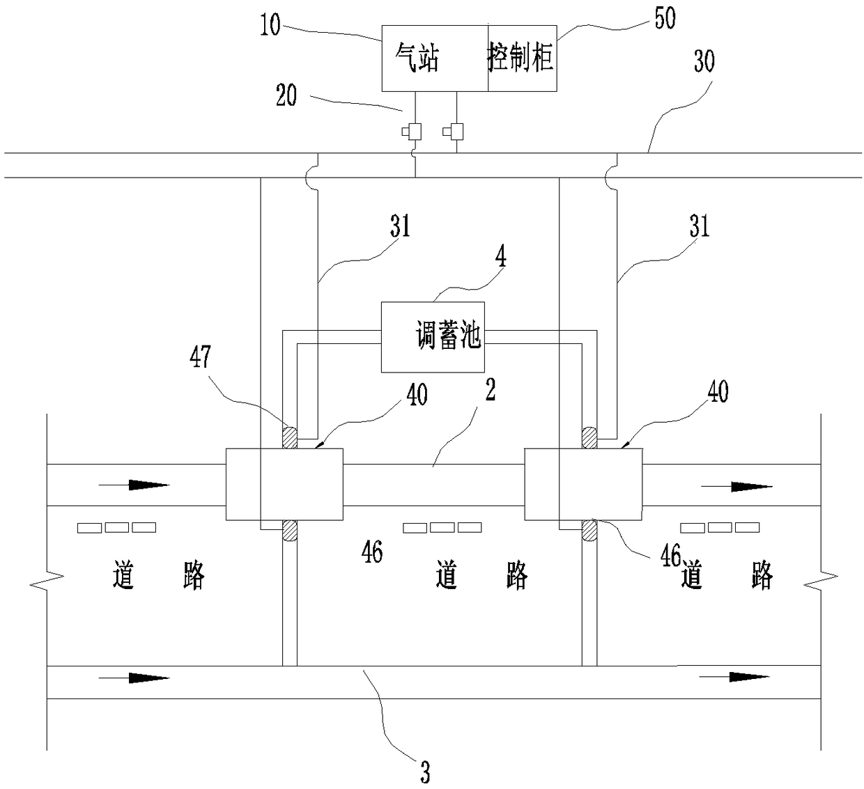
[0116] In this embodiment, on the basis of implementing 1 and 2, at least two diversion wells 40 will be arranged at intervals along the municipal rainwater pipe 2, and the diversion well A and the diversion well B will be illustrated as examples; wherein,
[0117] When the diversion well 40 is provided with the second pneumatic shut-off device 46 and the third pneumatic shut-off device 47, namely the first form:
[0118] The gas delivery pipeline includes a second gas delivery main pipe, a third gas delivery main pipe and several gas delivery branch pipes 31, and the second pneumatic shut-off devices 46 of all split wells 40 communicate with the second gas delivery main pipe 30 through the gas delivery branch pipes respectively. , the third pneumatic shut-off devices 47 of all split wells 40 communicate with the third gas delivery main pipe 30 through the gas delivery branch pipe respectively, the second control valve 20 is arranged on the second gas delivery main pipe 30, and...
PUM
 Abstract
Description
Claims
Application Information
 - R&D
- Intellectual Property
- Life Sciences
- Materials
- Tech Scout
- Unparalleled Data Quality
- Higher Quality Content
- 60% Fewer Hallucinations
Browse by: Latest US Patents, China's latest patents, Technical Efficacy Thesaurus, Application Domain, Technology Topic, Popular Technical Reports.
© 2025 PatSnap. All rights reserved.Legal|Privacy policy|Modern Slavery Act Transparency Statement|Sitemap|About US| Contact US: help@patsnap.com