A stealth exhaust pipe with adjustable tapered cavity

A conical cavity, exhaust pipe technology, applied in jet propulsion devices, machines/engines, mechanical equipment, etc., can solve complex exhaust pipe and engine matching, stealth coating materials are easy to fall off, cannot cover high temperature parts, etc. It can improve the stealth performance of radar, avoid angular reflection, and improve the performance of infrared stealth.

Active Publication Date: 2020-09-22
XIAN AIRCRAFT DESIGN INST OF AVIATION IND OF CHINA
View PDF5 Cites 0 Cited by
  • Summary
  • Abstract
  • Description
  • Claims
  • Application Information

AI Technical Summary

Problems solved by technology

Generally, the axisymmetric nozzle with adjustable area realizes the adjustment of the nozzle area through the actuating mechanism and the fish scales of the nozzle expansion section, but the axisymmetric nozzle designed in this way cannot shield high-temperature components, and the high-temperature environment also brings stealth coating The covering material is easy to fall off, which brings many difficulties to the stealth design of the nozzle.
[0005] In order to make the nozzle have low infrared radiation and electromagnetic scattering characteristics, S-curve or double-S-curve nozzles are applied to the nozzle design, but generally S-curve nozzles are pipes whose area cannot be adjusted, although they have good stealth performance However, the thrust loss is relatively large. In addition, after the engine is installed with an S-bend nozzle, it will also bring more complicated matching problems between the exhaust pipe and the engine.

Method used


Image

  • A stealth exhaust pipe with adjustable tapered cavity
  • A stealth exhaust pipe with adjustable tapered cavity
  • A stealth exhaust pipe with adjustable tapered cavity

Examples


Embodiment Construction

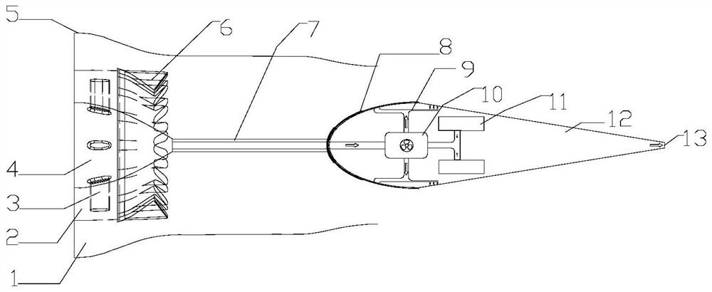
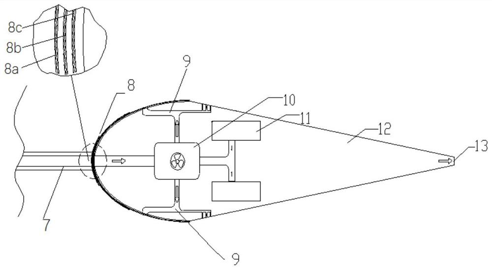
[0026] A stealth exhaust pipe with an adjustable tapered cavity, including an exhaust system, the exhaust system includes an outer duct 1, an inner duct 2, a support plate 3, a central cone 4, a nozzle wall 5 and a mixing 6, the outer duct 1 is set outside the inner duct 2, the central cone 4 is set inside the mixer 6, the support plate 3 is set outside the central cone 4, and also includes a telescopic sleeve 7, a tapered cavity Body 12 and aerosol injection device 10, the telescopic sleeve 7 is arranged on the top of the central cone 4, the telescopic sleeve 7 includes an inner sleeve and an outer sleeve, and the main function of the telescopic sleeve is to place the central cone The cooling air flow is introduced into the conical cavity 12, and the inner sleeve passes through the conical cavity 12 to communicate with the aerosol injection device 10 arranged inside the conical cavity 12, and the inside of the conical cavity 12 Several aerosol storage devices 11 are provided,...


PUM


Abstract

The invention discloses a stealth exhaust pipe provided with an adjustable conical cavity. The exhaust pipe comprises an exhaust system; the exhaust system comprises an outer duct, an inner duct, a supporting plate, a central cone, a spraying pipe wall surface, a telescopic sleeve, the conical cavity and an aerosol injection device; the telescopic sleeve is arranged at the cone vertex of the central cone of the exhaust system and comprises an inner sleeve and an outer sleeve; the inner sleeve penetrates through the conical cavity to communicate with the aerosol injection device arranged insidethe conical cavity; a plurality of aerosol storage devices are arranged inside the conical cavity and communicate with the aerosol injection device; a plurality of aerosol discharging pipelines are connected onto the aerosol injection device; outlets of the aerosol discharging pipelines are arranged on the outer surface of the conical cavity; and an air pump is arranged inside the aerosol injection device. According to the exhaust pipe, the stealth requirement of an aircraft for the exhaust pipe is considered, and meanwhile, the problems that wave absorbing media are prone to loss and fallingdue to coating of high-temperature wall surfaces and the thrust loss is relatively high due to exhaust pipes adopting S-bend structures are avoided.

Description

technical field [0001] The invention relates to the technical field of aero-engine exhaust systems, in particular to a stealth exhaust pipe with an adjustable tapered cavity. Background technique [0002] The stealth performance of the aircraft is mainly composed of two parts: infrared stealth and radar stealth. The radar stealth capability is mainly determined by the radar cross section of the aircraft, which is related to the aircraft's geometric parameters, physical parameters, radar wave parameters, and the relative attitude angle between the aircraft and the radar. As a typical cavity structure, the tail nozzle of the exhaust system has become one of the strong scattering sources of the aircraft, and it is also the main scattering source of the aircraft backward. In addition, the infrared characteristics of the aircraft are mainly affected by the tail nozzle of the exhaust system in the 3μm-5μm band. The tail nozzle of the engine is the main source of infrared radiati...

Claims


Application Information

Patent Timeline
Patent Type & Authority Patents(China)
IPC IPC(8): F02K1/82F02K1/78F01D25/30F02K1/15
CPCF01D25/30F02K1/15F02K1/78F02K1/825
Inventor 高翔周红邓文剑
Owner XIAN AIRCRAFT DESIGN INST OF AVIATION IND OF CHINA
Why Eureka
Try Eureka