The gear and the rack with the structure of the slide groove reciprocate to the automatic limit device at the end point

An automatic limit and reciprocating motion technology, applied in the direction of transmission, friction transmission, belt/chain/gear, etc., can solve the problems of too simple setting, no substance, weakened rack toughness, etc., and achieve simple and practical structure, convenient Maintenance, easy sealing effect

Active Publication Date: 2021-11-30
DALIAN GUANGDI TECH CO LTD
View PDF5 Cites 0 Cited by
  • Summary
  • Abstract
  • Description
  • Claims
  • Application Information

AI Technical Summary

Problems solved by technology

"In the setting of "the transmission rack is composed of the upper connecting block 5 of the rack and the rack part 8 connected by bolts through the slideway in the middle notch of the object connecting plate 1," there is no substantive setting of "the upper connecting block 5" function, the function of its setting can be set and replaced in " rack part 8 " completely, and cause the manufacturing process of rack part too much, the tenacity of rack weakens; The bottom guide groove of the rack part 8 is connected and fixed on the dragging object connecting plate 1. Its technical characteristics cannot be effectively utilized in the equipment manufacturing process; secondly, in the document [0006], "the slideways on both sides of the middle notch of the dragging object connecting plate 1 are arranged at the junction of the upper connecting block 5 of the rack and the rack part 8 to guide the In the groove, the "and" rack slideway and the slideway of the fixed plate 6 are arranged in the guide grooves at the bottom of both sides of the rack part 8; the spring device 7 and the rack are arranged at both ends of the front of the slot in the middle of the dragging object connecting plate 1. In the limit stop device 9, there are two slides in the "drive rack", and the two slides solve the same problem, which is a design defect, especially the middle notch of the "drag object connecting plate 1 The comprehensive setting of the "drag object connecting plate 1" with the spring device 7 and the rack limit stop device 9" at both ends of the front becomes the main fixed structure in the technical implementation, and the "drag object connecting plate 1" is set too much. ", which limits the practical application of its technical principles, and is not convenient for the sealing of the main structure

Method used


Image

  • The gear and the rack with the structure of the slide groove reciprocate to the automatic limit device at the end point
  • The gear and the rack with the structure of the slide groove reciprocate to the automatic limit device at the end point
  • The gear and the rack with the structure of the slide groove reciprocate to the automatic limit device at the end point

Examples


Embodiment Construction

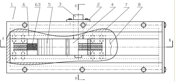
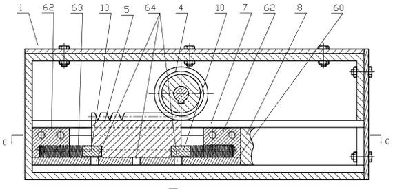
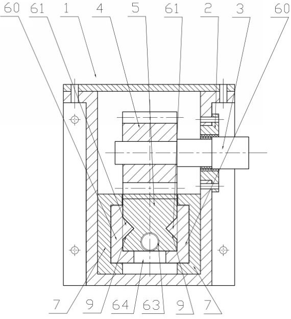
[0029] The specific embodiment of the present invention is described below in conjunction with accompanying drawing, as figure 1 , figure 2 , image 3 , Figure 4 Shown: The gear and the rack with the slideway groove structure reciprocate to the end point automatic limit device, including the housing 1, the fixed seat 2, the main shaft 3, the gear 4, the rack 5, the automatic limit drive block 6, the fixed slide Track slot 7 and drag object 8.

[0030] The housing 1 is a sealed housing, and the main body structure of the housing 1 is set as a square, and can also be set as a circle or other shapes. One side of the housing 1 is provided with a fixing seat 2, and the fixing seat 2 passes through the The screw is fixedly connected to the housing 1, the fixed seat 2 is fixedly connected to the main shaft 3, and the main shaft 3 passes through the housing 1 and is fixedly connected to the gear 4, and the main shaft 3 provides power for the rotational movement of the gear 4 by c...


PUM


Abstract

The invention relates to a device for automatically limiting position after a gear and a rack reciprocate in a straight line to a terminal under the action of force, in particular to an automatic position limiting device for a gear and a rack with a slideway groove structure when reciprocating to an end. Including housing, fixed seat, main shaft, gear, rack, automatic limit drive block, fixed slideway groove and dragging object, one side of the housing is provided with a fixed seat, the fixed seat is fixedly connected to the main shaft, and the main shaft passes through the housing Connected with the gear, the gear and the rack are meshed; the inside of the housing is equipped with an automatic limit drive block, the rack is set at the inner middle position of the automatic limit drive block, and there are fixed slideway grooves on both sides of the automatic limit drive block. The fixed slideway groove is fixed on the housing, and the end of the automatic limit drive block is connected with the dragging object. The automatic limit driving block of the device is the main structure, which is simple and practical in structure, and is convenient for maintenance; the automatic limit driving block connects different dragging objects at different positions, and is suitable for the connection of dragging objects in any equipment that does linear reciprocating motion.

Description

technical field [0001] The invention relates to a device for automatically limiting a gear and a rack when they linearly reciprocate to a terminal under the action of force, in particular to an automatic limiting device for a gear and a rack with a slideway groove structure when reciprocating to an end. Background technique [0002] Nowadays, many industrial equipment or institutions need a drive device capable of linear reciprocating motion to provide the required power. Commonly, there are electric drive, manual drive, hydraulic drive, and pneumatic drive; the hydraulic drive system is more complicated, and the pneumatic drive system requires compressed air. The auxiliary system costs a lot, and the pipeline is easy to freeze and block in the cold season, which affects the normal operation of the equipment and limits the application range. Electric and manual drives are usually screw mechanism and gear and rack drive mechanism, but electric drive equipment often has the ph...

Claims


Application Information

Patent Timeline
Patent Type & Authority Patents(China)
IPC IPC(8): F16H19/04H02K7/10
CPCF16H19/04F16H2019/046H02K7/10
Inventor 张希国
Owner DALIAN GUANGDI TECH CO LTD
Why Eureka
Try Eureka