Raster image projection method, three-dimensional reconstruction method and three-dimensional reconstruction system

A grating image and projection technology, applied in the field of three-dimensional measurement, to achieve the effects of high robustness, reduced times, and strong adaptability

Active Publication Date: 2019-02-15
SHENZHEN HUAHAN WEIYE TECH
View PDF12 Cites 17 Cited by
  • Summary
  • Abstract
  • Description
  • Claims
  • Application Information

AI Technical Summary

Problems solved by technology

[0004] The technical problem mainly solved by the present invention is how to improve the projection quality of the grating image in the existing 3D reconstruction, so as to ensure the imaging effect of the grating image projected onto the surface of the object

Method used


Image

  • Raster image projection method, three-dimensional reconstruction method and three-dimensional reconstruction system
  • Raster image projection method, three-dimensional reconstruction method and three-dimensional reconstruction system
  • Raster image projection method, three-dimensional reconstruction method and three-dimensional reconstruction system

Examples


Embodiment 1

[0042] The grating image projection method proposed by the present application will be described below through an embodiment, please refer to figure 1 , a grating image projection method, which includes steps S110-S120, which will be described respectively below.

[0043] Step S110, generating and projecting a raster image. The grating image generated here includes several rows of projection images, each projection image includes a plurality of periodic intervals distributed side by side, and each periodic interval includes grating fringes formed in the periodic interval according to a preset fringe distribution function. In one embodiment, see figure 2 , step S110 may include steps S111-S114, which are described as follows:

[0044] In step S111 , several rows of projection images are constructed, so that each projection image includes a plurality of periodic intervals distributed in parallel, and the encoding code value g of each periodic interval is preset. In this embo...

Embodiment 2

[0078] Here we will introduce a 3D reconstruction method based on the above-mentioned raster image projection method. For details, please refer to Image 6 , the three-dimensional reconstruction method may include steps S210-S230, which will be described respectively below.

[0079] In step S210, the object to be inspected is projected according to the grating image projection method in Embodiment 1 until the preset number of projections is reached, and a measurement image formed by projecting each generated grating image on the object to be inspected is obtained.

[0080] In this embodiment, the number of projections may be limited by the number M of raster images, that is, the raster images are projected one by one as many raster images are generated.

[0081] Step S220, acquiring the grayscale intensity of each pixel in each measurement image to construct a grayscale distribution vector of each measurement image.

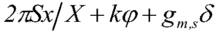
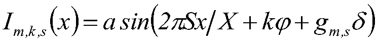
[0082] For example, for the fringe distribution function i...

Embodiment 3

[0100] Correspondingly, a 3D reconstruction system is disclosed here according to the 3D reconstruction method disclosed in Embodiment 2, please refer to Figure 7 , the three-dimensional reconstruction system includes a projection device 31, an image acquisition device 32 and an arithmetic processing device 33, which will be described separately below.

[0101]The projection device 31 is used to project the object D1 to be detected according to the grating image projection method in the first embodiment until the preset number of projections is reached. The projection device 31 preferably adopts a coded grating projection device, and uses a DMD module or an LCOS module for projection. In order to adapt to different application scenarios, the projection device 11 can project a variety of structured lights of different colors, such as white structured light, blue Structured light and red structured light, wherein the blue structured light may have a wavelength of 405nm, and the...


PUM


Abstract

The invention discloses a raster image projection method, a three-dimensional reconstruction method and a three-dimensional reconstruction system. On the one hand, a grating stripe in each period of araster image has a phase shifting characteristic since the raster image projection method can continuously update a fringe distribution function for forming the grating stripe, thereby facilitating the progressive changes of the grating stripe according to the projection light intensity, and facilitating to create high quality projections. On the other hand, the problems of blurring, dirt and diffuse reflection on a surface of an object can be effectively overcome by adopting the raster image projection since the generated raster image retains the advantages of the original phase shifting method, and the raster image projection method is more adaptable to scenes such as the reflection. In addition, the three-dimensional reconstruction system can obtain a clear surface contour of the object since the three-dimensional reconstruction method utilizes the raster image projection technology, and is advantageous for decomposing a projection coordinate of each pixel point, thereby obtainingthe high-precision three-dimensional reconstruction effect.

Description

technical field [0001] The invention relates to the field of three-dimensional measurement, in particular to a grating image projection method and device for three-dimensional reconstruction. Background technique [0002] Three-dimensional reconstruction is the process of applying certain means and methods to scan the measured object to obtain its surface space coordinates, so as to establish a mathematical model suitable for computer representation and processing. The traditional method usually uses a three-dimensional coordinate machine to extract the three-dimensional contour of the object. Although this type of method has the benefits of high measurement accuracy, it also has the disadvantages of long contact measurement cycle and is not suitable for soft object surface measurement. At present, optical means are mostly used to extract 3D contours for 3D reconstruction. This method can not only measure objects without contact, but also has the characteristics of high meas...

Claims


Application Information

Patent Timeline
Patent Type & Authority Applications(China)
IPC IPC(8): G01B11/25
CPCG01B11/254
Inventor 杨洋
Owner SHENZHEN HUAHAN WEIYE TECH
Why Eureka
Try Eureka