
Experimental device for vibration dynamics modal test

A modal test and experimental device technology, applied in vibration testing, measuring devices, testing of machine/structural components, etc., can solve the problems of complex design, complicated change and disassembly, single excitation point, etc., to achieve convenient disassembly, shape The effect of good applicability and simple structure

Pending Publication Date: 2019-02-15
GUANGZHOU UNIVERSITY
View PDF0 Cites 0 Cited by
  • Summary
  • Abstract
  • Description
  • Claims
  • Application Information

AI Technical Summary

Problems solved by technology

However, the experimental working conditions (such as boundary conditions and excitation methods) of the traditional modal test device are single, usually using a cantilever structure with one end fixed and one end free, and a single-point or fixed-point excitation method; on the other hand, the constraints of the experimental device The change and disassembly of the method are also more complicated; the excitation point is often relatively single due to the fixation of the excitation equipment, and it is inconvenient to change the excitation position of the exciter; the design is complicated and the processing cost is high

Method used


Image

  • Experimental device for vibration dynamics modal test
  • Experimental device for vibration dynamics modal test
  • Experimental device for vibration dynamics modal test

Examples


Embodiment

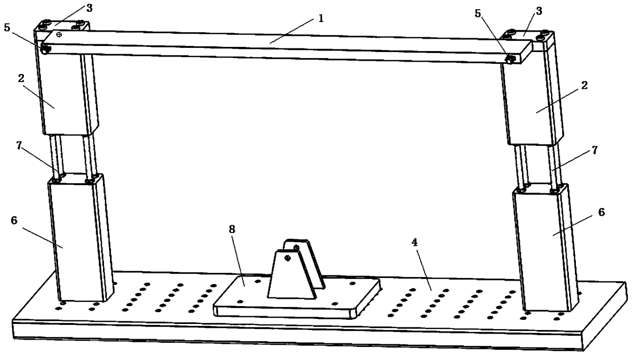
[0022] Such as figure 1 As shown, the present invention includes an experimental model (in this embodiment, a horizontal experimental steel beam 1 is selected), a beam end clamp, a height-adjustable base column and an experimental base floor 4, wherein square holes are preset at both ends of the horizontal experimental steel beam There are two groups of beam end clamps, each set of beam end clamps includes clamp upper block 3 and clamping rod 5, the cross section of the clamping rod of the first set of beam end clamps is square, and the clamping rod of the second set of beam end clamps The cross-section of the holding rod is circular, and threads matching the bolt caps are provided at the end of the holding rod, such as figure 2 , 3 shown.

[0023] The clamp upper block of each set of beam end clamps is connected with the horizontal experimental steel beam through the clamping rod and the bolt cap. Hole slots are joined in an inscribed form. When the clamping rod with squ...


PUM


Abstract

The invention relates to a modal test technology, in particular to an experimental device for a vibration dynamics modal test. The device comprises an experiment model, two sets of clamps, base columns and an experiment base bottom plate, wherein square hole grooves are formed in the two ends of the experiment model; each set of clamps comprises a clamp upper block and a clamping rod; the cross section of the clamping rod of the first set of the clamps is square; the cross section of the clamping rod of the second set of the clamps is round; the clamp upper block of each set of the clamps areconnected with the experiment model through the clamping rod; the clamping rods with the square cross sections are matched with the square hole grooves in size; the clamping rods with the round crosssections are combined with the square hole grooves in an internally tangent mode; the clamp upper blocks are fixed with the base columns; and the base columns are connected with the experiment base bottom plate. The experimental device can flexibly change experimental working conditions and is convenient to mount and dismount.

Description

technical field [0001] The invention relates to modal test technology, in particular to an experimental device for vibration modal test. Background technique [0002] Modal test, also known as experimental modal analysis, is a vibration test performed to determine the modal parameters of a linear vibration system. Experimental modal analysis is mainly to measure the vibration response signal of the system through modal experiments, or measure the excitation signal and response signal of the system at the same time, and identify the modal parameters describing the dynamic characteristics of the system from the measured signals. Modal parameters are a description of the inherent characteristics of the vibration system in the frequency domain, generally referring to the natural frequency, damping ratio, mode shape, and modal quality of the system. [0003] Commonly used modal tests use a vibrator to excite the structure to be tested, generate an excitation force on the structu...

Claims


Application Information

Patent Timeline
IPC IPC(8): G01M7/02
CPCG01M7/02G01M7/027
Inventor 李智刘珍何运成
Owner GUANGZHOU UNIVERSITY
Learn More