
Scanning structure, laser radar and vehicle

A laser radar and vehicle technology, applied in the field of laser detection, can solve problems such as difficult to meet vehicle regulations, low reliability, high cost, etc., and achieve the effect of strong vibration resistance and low cost

Inactive Publication Date: 2019-02-15
JIANGSU INTELIGHT ELECTRONICS TECH
View PDF15 Cites 8 Cited by
  • Summary
  • Abstract
  • Description
  • Claims
  • Application Information

AI Technical Summary

Problems solved by technology

The mechanical design directly constitutes several shortcomings of the current laser radar: optical path debugging and assembly are complicated, the production cycle is long, and the cost remains high; the reliability of mechanical rotating parts in the driving environment is not high, and it is difficult to meet the strict regulations of the car. demanding

Method used


Image

  • Scanning structure, laser radar and vehicle
  • Scanning structure, laser radar and vehicle
  • Scanning structure, laser radar and vehicle

Examples


Embodiment Construction

[0044] The present invention will be described in detail below in conjunction with specific embodiments. The following examples will help those skilled in the art to further understand the present invention, but do not limit the present invention in any form. It should be noted that those skilled in the art can make several changes and improvements without departing from the concept of the present invention. These all belong to the protection scope of the present invention.

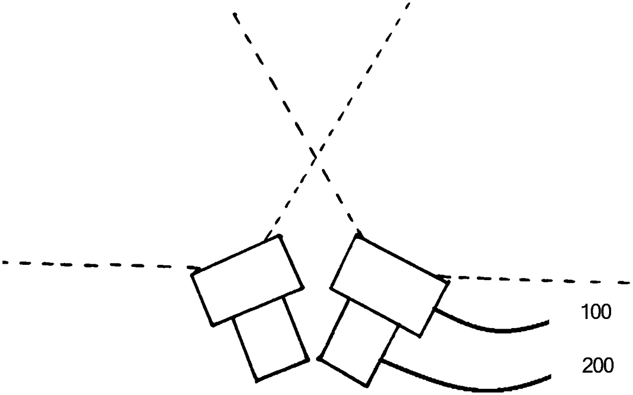
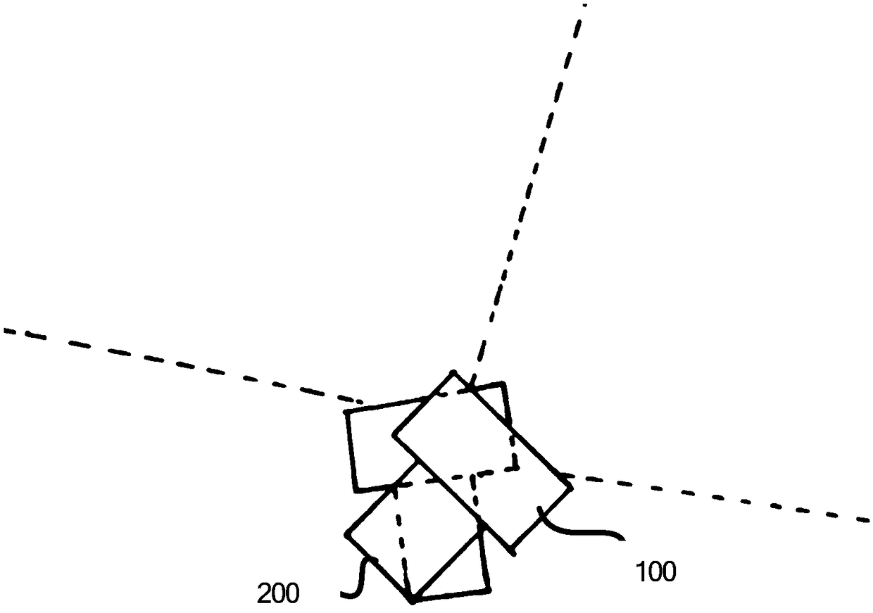
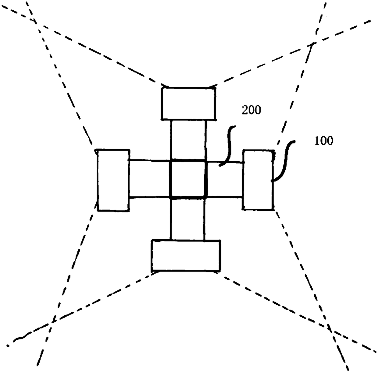
[0045] see figure 1 What is shown is a spliced ​​scanning structure of two-chip spatial light modulators, and the control device synchronously controls the transmitting device, the scanning unit, and the receiving device. The emitting device includes a laser. The laser pulses emitted by the two lasers are collimated and / or shaped by the optical system and then input to two scanning units respectively. Each scanning unit has a spatial light modulator and an optical system. The beam can generate a scanni...


PUM


Abstract

The invention provides a scanning structure, which comprises a plurality of scanning units. Each scanning unit has its own scanning area. The scanning units scan an environment with an emitted light beam by means of splicing to obtain a spliced scanning area. The splicing refers to that the propagation paths of the edge light of every two adjacent scanning areas overlap or coincide after emissionfor a certain distance. The invention further provides a corresponding piece of laser radar and a vehicle. Multiple spatial light modulators are spliced at a certain angle, and a wide or 360-degree scanning range can be achieved without a rotary mechanical structure. Arbitrary beam can be output. The ability to resist vibration is strong. A high-precision, high-efficiency and high-stability scanning effect can be achieved with fewer lasers. The blind area at the splicing point can be controlled to be very small, and has little effect on the scanning. The effects of stable operation, low cost and high precision are achieved.

Description

technical field [0001] The invention relates to the technical field of laser detection, in particular to a scanning structure, a laser radar and a vehicle. Background technique [0002] Lidar has the advantages of extremely high angular resolution and distance resolution, high speed resolution, wide range of speed measurement, multiple images of targets, strong anti-interference ability, and smaller volume and weight than microwave radar. This enables lidar to accurately measure the position, motion state and shape of the target, detect, identify, distinguish and track the target. In recent years, with the development of artificial intelligence, the rise of autonomous driving, assisted driving, commercial drones and intelligent robots has promoted the application of lidar in the civilian field. [0003] The vehicle-mounted lidars currently available on the market are basically mechanical, and their typical feature is that they have mechanical parts and can rotate. The mech...

Claims


Application Information

Patent Timeline
Patent Type & Authority Applications(China)
IPC IPC(8): G01S7/481
CPCG01S7/4817
Inventor 陈凯邱家铖谈顺毅陈志龙
Owner JIANGSU INTELIGHT ELECTRONICS TECH
Learn More