Magnetic-adjustable dual-mode bandpass filter
A filter and mode band technology, applied in waveguide-type devices, electrical components, circuits, etc., can solve the problems of size and production cost, frequency selectivity and poor stop-band characteristics, etc.
- Summary
- Abstract
- Description
- Claims
- Application Information
AI Technical Summary
Problems solved by technology
Method used
Image
Examples
Embodiment
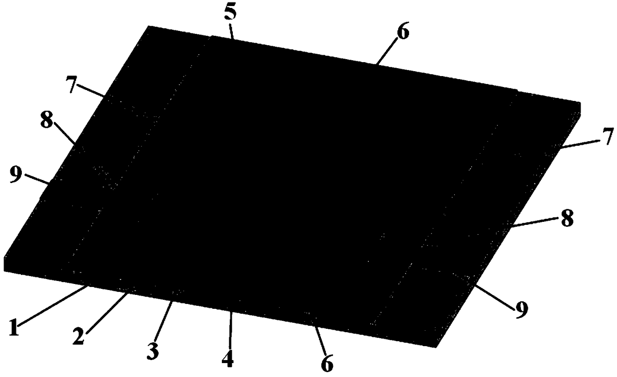
[0027] The structure of the magnetically tunable dual-mode bandpass filter in this embodiment is as follows figure 1 As shown, the dielectric substrate 2 adopts a Rogersduroid 6202 substrate with a thickness of 0.726 mm, and its relative dielectric constant ε r =2.9, loss tangent tanδ = 0.0015.
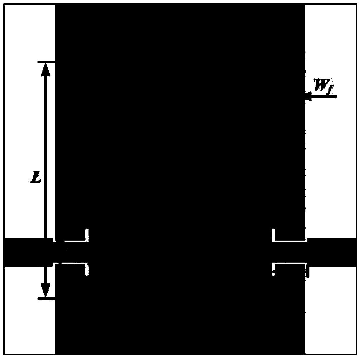
[0028] Specifically, in this embodiment, the dual-mode resonant cavity 5 is a rectangular substrate integrated waveguide resonator; the metalized through-hole array 4 is composed of cuboid metalized through holes, and the metalized through-hole array 4 is The length of the through hole is 0.9mm, and the distance between adjacent metallized through holes is 0.4mm; the through holes in the dual-mode resonant cavity 5 close to the boundary through hole array 4 and the ferrite in the through holes The shape is a rectangular parallelepiped; the first ferrite 6 and the second ferrite 7 both use microwave yttrium iron garnet (YIG) ferrite; the upper and lower surfaces of the ferrite are covered ...
PUM
| Property | Measurement | Unit |
|---|---|---|
| thickness | aaaaa | aaaaa |
| length | aaaaa | aaaaa |
| relative permittivity | aaaaa | aaaaa |
Abstract
Description
Claims
Application Information
 - R&D
- Intellectual Property
- Life Sciences
- Materials
- Tech Scout
- Unparalleled Data Quality
- Higher Quality Content
- 60% Fewer Hallucinations
Browse by: Latest US Patents, China's latest patents, Technical Efficacy Thesaurus, Application Domain, Technology Topic, Popular Technical Reports.
© 2025 PatSnap. All rights reserved.Legal|Privacy policy|Modern Slavery Act Transparency Statement|Sitemap|About US| Contact US: help@patsnap.com


