A Method for Automatic Power Flow Control of Regional Power Grid Lines

A technology for regional power grids and lines, applied in circuit devices, AC network circuits, electrical components, etc., can solve problems such as difficulty in meeting the requirements of power grid intelligence, improve automation capabilities, enhance safety, and reduce the possibility of misoperation. Effect

Active Publication Date: 2021-06-01
YIBIN POWER SUPPLY COMPANY STATE GRID SICHUAN ELECTRIC POWER +1
View PDF5 Cites 0 Cited by
  • Summary
  • Abstract
  • Description
  • Claims
  • Application Information

AI Technical Summary

Problems solved by technology

With the continuous expansion of the grid scale, the traditional manual monitoring and control mode has been difficult to meet the intelligent requirements of grid dispatching

Method used


Image

  • A Method for Automatic Power Flow Control of Regional Power Grid Lines
  • A Method for Automatic Power Flow Control of Regional Power Grid Lines
  • A Method for Automatic Power Flow Control of Regional Power Grid Lines

Examples


Embodiment 1

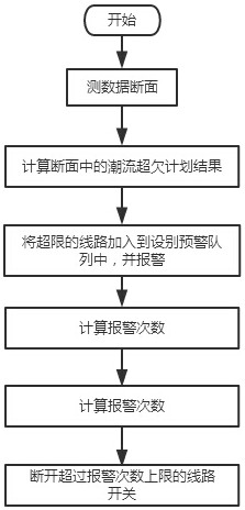
[0046] The present invention is realized through the following technical solutions, as Figure 1-Figure 2 As shown, a method for automatic power flow control of regional power grid lines specifically includes the following steps:

[0047] Step F1: get cyc SCADA measurement section data of the power grid and planned power flow data of each line and main transformer of the power grid with a period of one second, and calculation of the power flow over and under plan results of the entire network and each line;

[0048] Step F2: Add the lines whose power flow overrun plan value exceeds the set percentage to the equipment early warning queue list and give an alarm prompt, and calculate the accumulated alarm times of the lines in the equipment early warning queue list according to the set time interval;

[0049] Step F3: When the accumulative number of alarms of a certain line in the equipment early warning queue list exceeds the set upper limit of the number of early warnings, the...

Embodiment 2

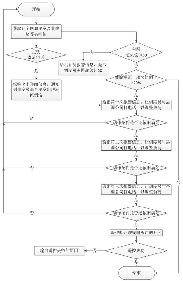
[0054] This embodiment is further optimized on the basis of the above embodiments, such as Figure 1-Figure 2 As shown, the step F1 specifically includes the following steps:

[0055] Step F11: Obtain t from grid SCADA cyc The measurement section data with a period of one second; the t cyc Set by the user, the default value is 10s;

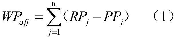
[0056] Step F12: Calculating the power flow overrun plan value WP of the whole network in the section off ;

[0057]

[0058] In formula (1), RP j Indicates the active power measurement value of the gateway line or main transformer; PP j Indicates the active power planning value of the grid gateway line or main transformer, which is obtained from the grid active power planning function module; n indicates the total number of grid gateway lines and main transformers; j indicates each gateway line and main transformer;

[0059] Step F13: When the power flow of the whole network exceeds the planned value WP off Greater than the upper limit ...

Embodiment 3

[0072] This embodiment is further optimized on the basis of the above embodiments, such as Figure 1-Figure 2 As shown, the step F2 specifically includes the following steps:

[0073] Step F21: When the power flow of any line exceeds the percentage of planned value | LP off-k |≥LP max , then add the line to the equipment warning queue; LP max is the upper limit of the line power flow exceeding the planned value percentage; the LP max Set by the user, the default is 20%;

[0074] Step F21-1: When any line described in step F21 does not exist in the equipment early warning queue, add the line to the equipment early warning queue; set the continuous overtime time CT of the line off-k =0, cumulative alarm times CA off-k = 0;

[0075] Step F21-2: If any of the lines described in step F21 already exists in the equipment warning queue, then correct the line’s continuous time of exceeding the plan and the cumulative number of alarms of the line;

[0076] Step F21-2-1: In step F...


PUM


Abstract

The invention discloses a method for automatically controlling the power flow of regional power grid lines, which specifically includes the following steps: acquiring the SCADA measurement section data of the power grid and the planned power flow data of each line and main transformer of the power grid, and calculating the whole network and each line The result of the power flow overrun plan; add the lines with the power flow overrun plan value exceeding the set percentage to the equipment early warning queue table and give an alarm prompt, and calculate the number of alarms accumulated by the lines in the equipment early warning queue table according to the set time interval; in the equipment early warning When the cumulative number of alarms of a line in the queue table exceeds the set upper limit of warning times, the switch connected to the line is automatically disconnected by remote control operation, and the automatic closed-loop control of the line flow is completed. The invention proposes a method for matching end-face time of power grid SCADA and PMU measurement data, realizes real-time judgment, intelligent early warning and automatic control of regional power grid power flow control, not only ensures control safety, but also improves automation capability of power grid power flow control.

Description

technical field [0001] The invention relates to the technical field of electric power system scheduling automation, in particular to an automatic control method for power flow of regional power grid lines. Background technique [0002] One of the responsibilities of regional power grid dispatching is the power flow control of the regional power grid, that is, the power flow of each line and main transformer in the regional power grid is controlled within a certain range of the power flow planning value, so as to meet the intelligent requirements of power grid operation security and economy. With the continuous expansion of the grid scale, the traditional manual monitoring and control mode has been difficult to meet the intelligent requirements of grid dispatching. Therefore, it is urgent to realize the automatic control function of power flow in the smart grid dispatching automation system (EMS), track the operation status of the power grid in real time, and perform online a...

Claims


Application Information

Patent Timeline
Patent Type & Authority Patents(China)
IPC IPC(8): H02J3/00H02J3/06
CPCH02J3/00H02J3/06H02J3/003Y02E40/70Y02E60/00Y04S10/22
Inventor 华永东胡晓松王鹏陈伟汤磊
Owner YIBIN POWER SUPPLY COMPANY STATE GRID SICHUAN ELECTRIC POWER
Why Eureka
Try Eureka