
Vertical step type bicycle

A bicycle and frame technology, applied in the field of upright stepping bicycles, can solve the problems of lumbar and cervical spine damage, damage to health, and difficult control, etc., and achieve the effects of high work efficiency, high safety, and simple transmission structure

Active Publication Date: 2019-02-19
张欣
View PDF9 Cites 2 Cited by
  • Summary
  • Abstract
  • Description
  • Claims
  • Application Information

AI Technical Summary

Problems solved by technology

Because this kind of bicycle needs to be ridden in a sitting position, it has the following defects: 1) Riding with arched back for a long time will cause damage to the lumbar spine and cervical spine; 2) Sitting on the saddle for a long time will easily compress the blood flow of the legs Unsmooth and squeezed perineal parts lead to the occurrence of diseases such as the prostate gland, which will actually damage the health of the body; 3) Due to the high center of gravity, poor stability, and difficult manipulation, it is difficult for beginners to learn, and it is not suitable for children and the elderly; 4) When riding, the cyclist is sitting on the saddle. If there is an emergency, it is difficult to abandon the car to avoid danger; When the pedals are on a vertical plane, the torque is zero, which belongs to the dead point of force. Although the torque is the largest when the left and right pedals are on a horizontal plane, it is very laborious to step on, and has the defects of high energy consumption and low work efficiency
It can be seen from the above that although the above-mentioned patented technology can drive the bicycle by standing and walking, its structure is complex, bulky, and work efficiency is low. In particular, the use of a spring return method reduces reliability.

Method used


Image

  • Vertical step type bicycle
  • Vertical step type bicycle
  • Vertical step type bicycle

Examples


Embodiment

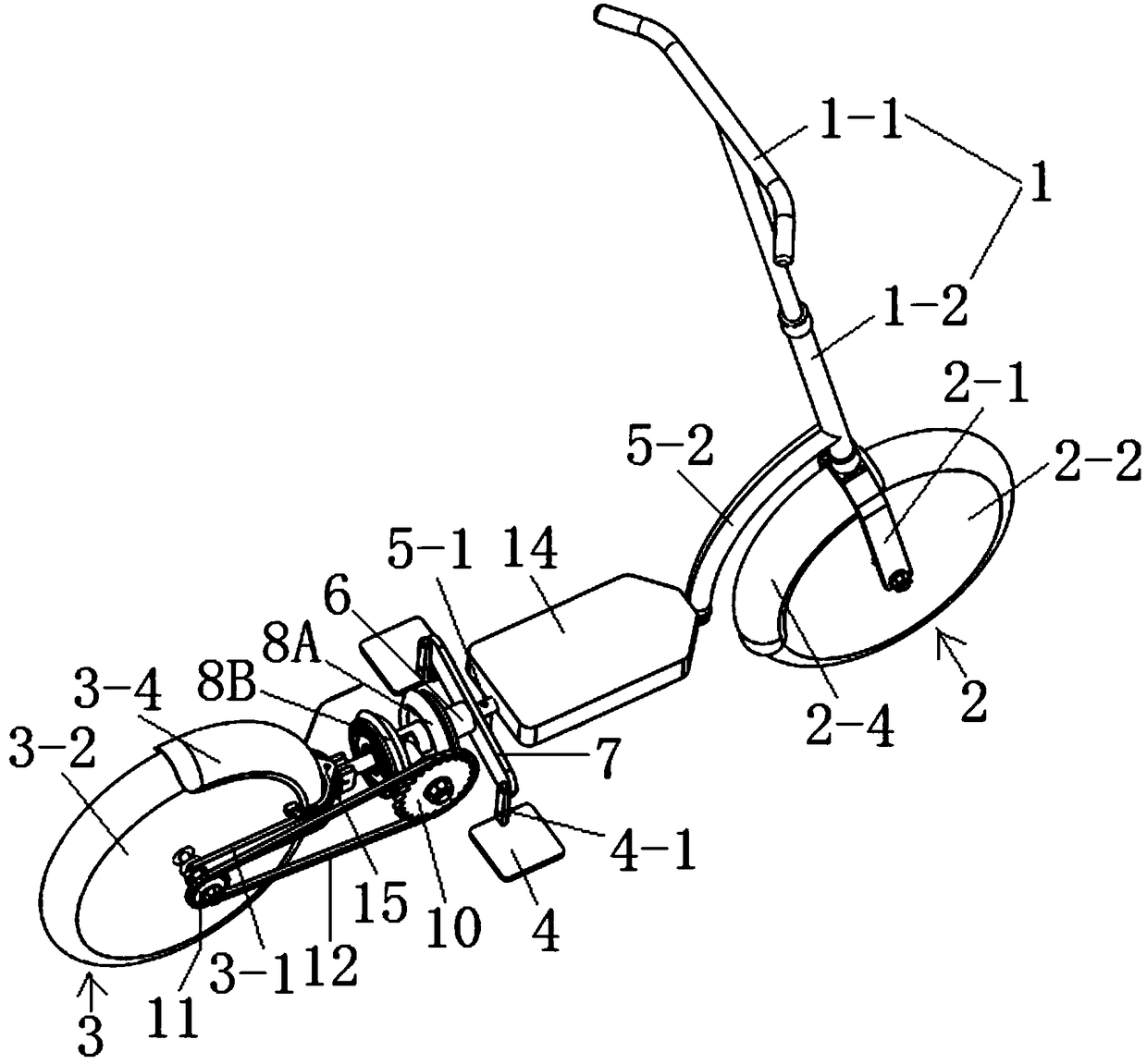
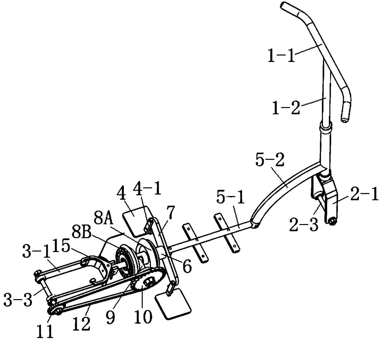
[0033] Such as figure 1 Shown: an upright stepping bicycle provided by the present invention, comprising a handlebar assembly 1, a front wheel assembly 2, a rear wheel assembly 3, a pedal 4 and a vehicle frame 5, the handlebar assembly 1 includes a handle 1-1 and lifting adjustment rod 1-2, the front wheel assembly 2 includes a front fork 2-1, a front wheel 2-2, a front axle 2-3 and a front fender 2-4, and the rear wheel assembly 3 comprises a rear fork 3-1, a rear wheel 3-2, a rear axle 3-3 and a rear fender 3-4.

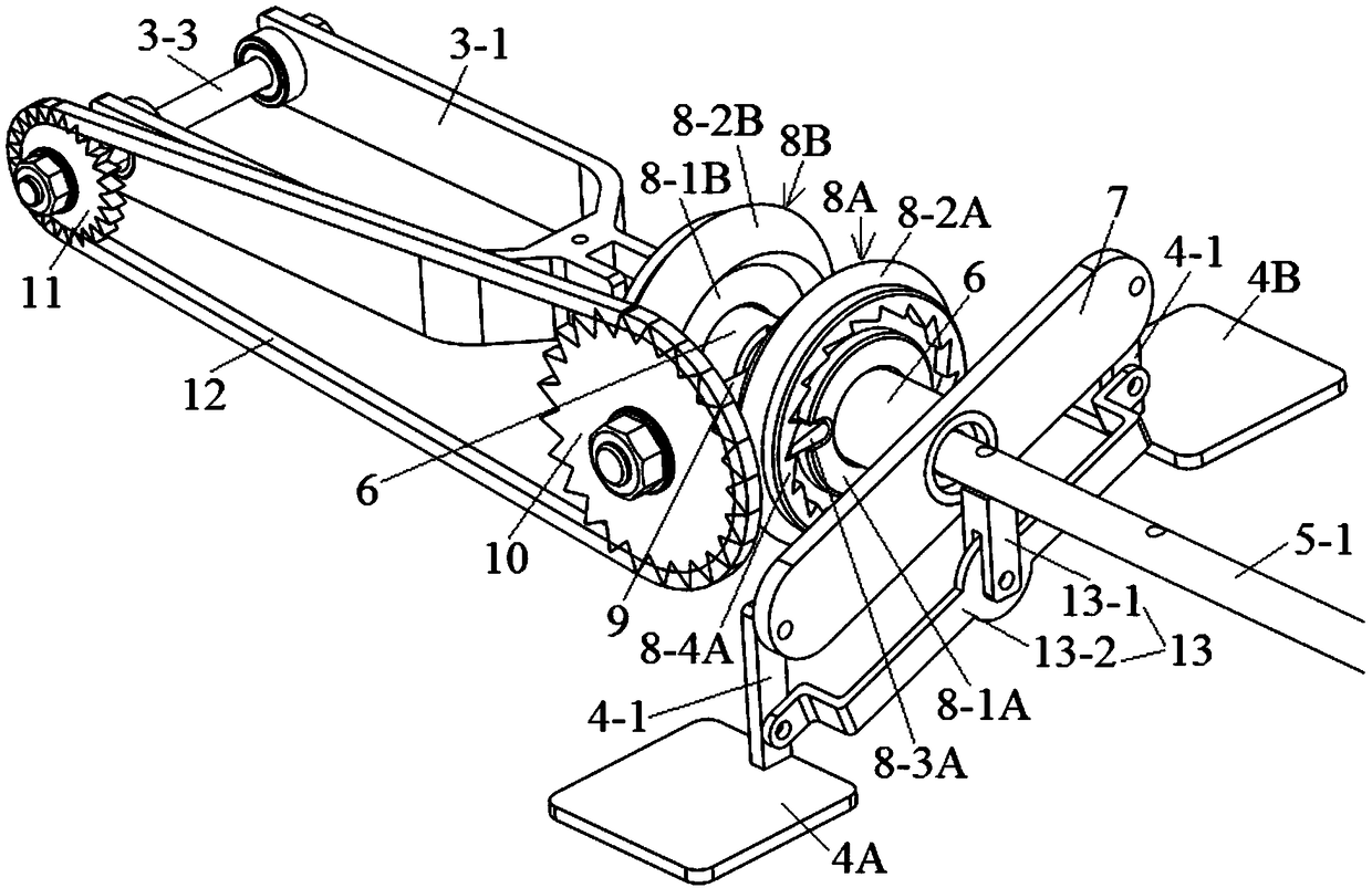
[0034] Please reunite Figure 1 to Figure 6 Shown:

[0035] In this embodiment, the vehicle frame 5 includes a longitudinal fixed shaft 5-1 and an arc-shaped connecting frame 5-2, the front fork 2-1 is fixedly connected with the lifting adjustment rod 1-2, and the arc-shaped connecting frame The front end of 5-2 is fixedly connected with the lifting adjustment rod 1-2, the rear end of the arc connecting frame 5-2 is fixedly connected with the front end of the lo...


PUM


Abstract

The invention discloses a vertical step type bicycle. The bicycle comprises a handlebar assembly, a front wheel assembly, a rear wheel assembly, a pedal and a frame; the frame comprises a longitudinalfixed shaft, a rotating sleeve rotationally sleeves the longitudinal fixed shaft and is sleeved with a pedal connecting rod, a front unidirectional wheel and a rear unidirectional wheel from front toback in sequence, the front unidirectional wheel and the rear unidirectional wheel are a pair of mirror symmetrical driving wheels which are internally provided with single-acting ratchet mechanismsthrough meshing and externally provided with oblique teeth, an opening is formed in the portion, located between the front unidirectional wheel and the rear unidirectional wheel, of the rotating sleeve, a transverse fixed shaft is vertically fixedly arranged on the longitudinal fixed shaft located in the opening, the transverse fixed shaft is rotationally sleeved with a driven wheel, oblique teethmatched with the driving wheel are arranged on the driven wheel, the driven wheel is in transmission connection with a chain wheel sleeving the end of a rear axle, and the pedal is rotationally connected with the pedal connecting rod through a straight shank. The purpose that the bicycle is driven through a stand walking mode is achieved, and the body-building exercise effect is achieved.

Description

technical field [0001] The invention relates to a bicycle, in particular to an upright stepping bicycle. Background technique [0002] Due to today's advanced technology, although people's living standards are constantly improving, work pressure is also increasing, and the time for exercise and fitness is getting less and less. Most people's bodies are in a serious sub-health state, so they have both The pedal bicycle with fitness function has begun to be more and more popular as a travel tool for fitness. [0003] But the existing pedal bicycle is provided with a crank on the sprocket, and a pedal is set on the crank, and the left and right pedals are given the left and right pedals in turn, so that the pedal drives the crank, and then drives the sprocket to rotate, thus playing a role The purpose of cycling. Because this kind of bicycle needs to be ridden in a sitting position, it has the following defects: 1) Riding with arched back for a long time will cause damage to ...

Claims


Application Information

Patent Timeline
Patent Type & Authority Applications(China)
IPC IPC(8): B62M1/28B62M1/30
CPCB62M1/28B62M1/30
Inventor 刘跃宇张欣
Owner 张欣
Learn More