Novel rotor type concrete injection unit

A technology of concrete spraying machine and spraying unit, which is applied in earthwork drilling, wellbore lining, tunnel lining, etc. It can solve the problems of endangering the health of on-site workers, leaking a lot of spraying raw materials, and increasing air pollution, so as to save working time , smooth feeding and simple structure

Pending Publication Date: 2019-02-19
徐州大屯工贸实业有限公司
View PDF0 Cites 4 Cited by
  • Summary
  • Abstract
  • Description
  • Claims
  • Application Information

AI Technical Summary

Problems solved by technology

When the dry-sprayed concrete jetting machine is working, it mixes the cement and aggregates in proportion. After entering the jetting machine, the air is used to constrain the material through the nozzle, and it is pushed to the sprayed working surface at high speed, and the mixing water passes through the nozzle. The ring will be added, and its main structure includes chassis, walking wheels, rotor concrete sprayer body and nozzle device. The rotor concrete sprayer body mainly includes hopper, hopper seat, reducer and rotor body assembly. There are upper and lower overflow ports on the body of the machine, and the concrete material is easily discharged into the air from the upper and lower overflow ports; when the friction plate of the rotor body is worn, a lot of shotcrete raw materials will leak out from its circumference, and the friction plate will cause it to flow into the hopper. Against the wind, it impacts th

Method used


Image

  • Novel rotor type concrete injection unit
  • Novel rotor type concrete injection unit
  • Novel rotor type concrete injection unit

Examples


Embodiment Construction

[0031] In order to make the object, technical solution and advantages of the present invention clearer, the present invention will be further described in detail below with reference to the accompanying drawings and embodiments. However, it should be understood that the specific embodiments described here are only used to explain the present invention, and are not intended to limit the scope of the present invention.

[0032] Unless otherwise defined, all technical terms and scientific terms used herein have the same meaning as commonly understood by those skilled in the technical field of the present invention, and the terms used in the description of the present invention herein are only to describe specific implementations The purpose of the example is not intended to limit the present invention.

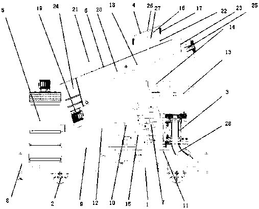
[0033] Such as figure 1As shown, a new type of rotor concrete spraying unit includes a chassis frame 1, a walking wheel 2 installed on the lower part of the chassis frame 1, a c...


PUM


Abstract

The invention discloses a novel rotor type concrete injection unit, and belongs to the field of anchoring and shotcreting support such as mine well lanes, railway (highway) tunnels and subways. The novel rotor type concrete injection unit comprises a chassis machine frame, walking wheels installed on the lower part of the chassis machine frame, a concrete injection machine body, an automatic setting accelerator adding mechanism, a dust removing device, a feeding device and a hydraulic tensioning device. Connecting bolts are installed at the left and right ends of the chassis machine frame, andthe chassis machine frame is provided with the dust removing device, a lower support rod, the feeding device, the automatic setting accelerator adding mechanism, an upper support rod, an injection machine body support frame, the hydraulic tensioning device and the concrete injection machine body from left to right in sequence. The novel rotor type concrete injection unit has the beneficial effects that the dust removal efficiency is high, tiny fine dust with the particle diameter larger than 5 microns can collected, and the dust removal efficiency can reach more than 99%; the novel rotor typeconcrete injection unit is flexible to use, can be arranged directly indoors and placed in small units near equipment; and the structure is relatively simple, the operation is relatively stable, theinitial investment is less, and the maintenance is convenient.

Description

technical field [0001] The invention relates to a novel rotor-type concrete spraying unit, which belongs to the field of bolting and spraying support for mine shafts, railway (road) road tunnels, subways and the like. Background technique [0002] Bolt shotcrete support is a new underground engineering technology, which has the advantages of low engineering cost, simple process, fast construction speed and low labor intensity. At present, it has been widely used in domestic and foreign mine shafts, railway (road) road tunnels, hydropower, subways and other projects. In order to achieve the purpose of shotcrete support, it is necessary to use a shotcrete machine to complete the spraying of concrete. The basic working principle of the spraying machine is to use the concrete pump to transport the concrete to the nozzle of the manipulator through the pipeline, and use the compressed air with the accelerator to spray the concrete to the wall of the sprayed roadway. my country's...

Claims


Application Information

Patent Timeline
IPC IPC(8): E21D11/10
CPCE21D11/105
Inventor 唐中猛袁传运唐宗浩张政倪强
Owner 徐州大屯工贸实业有限公司
Why Eureka
Try Eureka