
System and method for pumped-storage power generation by using underground goaf and chamber

A pumped-storage and goaf technology, applied in the directions of hydroelectric power generation, drainage, mining equipment, etc., can solve the problems of poor stability and continuity of power generation, waste energy, unable to maintain constant supply, etc., and achieve the effect of simple process.

Inactive Publication Date: 2019-02-19
KUNMING UNIV OF SCI & TECH
View PDF5 Cites 3 Cited by
  • Summary
  • Abstract
  • Description
  • Claims
  • Application Information

AI Technical Summary

Problems solved by technology

However, water energy, solar energy, and wind energy are affected by factors such as seasons, locations, and climates, which are random, intermittent, and volatile, and cannot maintain a stable constant supply, resulting in serious energy abandonment. In 2015, Yunnan Province only abandoned water and wind. , the abandoned photovoltaic power reached 15.3 billion kwh
Due to the poor stability and continuity of power generation, this poses a huge challenge to the real-time balance of the power system and the safe and stable operation of the power grid after wind power is connected to the grid.

Method used


Image

  • System and method for pumped-storage power generation by using underground goaf and chamber
  • System and method for pumped-storage power generation by using underground goaf and chamber

Examples


Embodiment 1

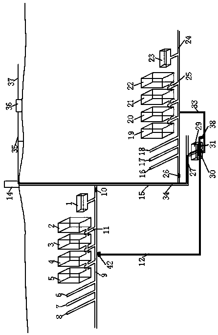
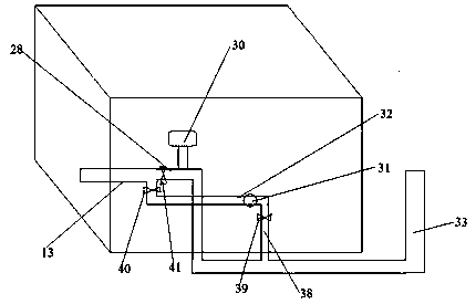
[0023] Embodiment 1: as figure 1 and figure 2 As shown, a system for pumped storage power generation using underground mined-out areas and chambers, including surface well towers 14, shafts 15, surface power lines 35, surface power stations 36, power lines 34, power generation chambers 29, upper The water storage space and the lower water storage space, the shaft 15 is located below the surface well tower 14, the power generation chamber 29 is located at the bottom of the shaft 15, the shaft 15 communicates with the power generation chamber 29 through the connecting roadway III 27, and the power generation chamber 29 is provided with Water pipeline II13, water pipeline III28, water pipeline IV, water pipeline V32, water pipeline VI38, water turbine generator 30 and water pump 31, the water turbine of water turbine generator 30 is arranged in water pipeline III28, and the water pump 31 is set on the water pipeline V32, the upper water storage space is located on the upper par...

Embodiment 2

[0027] Embodiment 2: as figure 1 and figure 2 As shown, a system for pumped storage power generation using underground mined-out areas and chambers, including surface well towers 14, shafts 15, surface power lines 35, surface power stations 36, power lines 34, power generation chambers 29, upper The water storage space and the lower water storage space, the shaft 15 is located below the surface well tower 14, the power generation chamber 29 is located at the bottom of the shaft 15, the shaft 15 communicates with the power generation chamber 29 through the connecting roadway III 27, and the power generation chamber 29 is provided with Water pipeline II13, water pipeline III28, water pipeline IV, water pipeline V32, water pipeline VI38, water turbine generator 30 and water pump 31, the water turbine of water turbine generator 30 is arranged in water pipeline III28, and the water pump 31 is set on the water pipeline V32, the upper water storage space is located on the upper par...

Embodiment 3

[0033] Embodiment 3: A method for generating electricity using a pumped-storage power generation system in underground gobs and chambers, the specific steps are:

[0034] (1) Water is introduced into the lower roadway I, lower roadway II, lower roadway III, and lower mined-out area I of the lower water storage space through the vertical shaft through the water pipeline III, the water pipeline IV, the water pipeline VII and the lower level entry , lower goaf II, lower goaf III, lower goaf IV and lower chambers for storage;

[0035] (2) During the low peak period of electricity consumption, close the valve I on the water delivery pipeline I and the valve II on the water delivery pipeline III, open the valve III on the water delivery pipeline V and the valve IV on the water delivery pipeline VI, The surplus power of the power grid is sent to the water pump through the transmission cable, the surface transmission station, the surface transmission line and the transmission line in ...


PUM


Abstract

The invention relates to a system and method for pumped-storage power generation by using an underground goaf and a chamber, and belongs to the technical field of mining and energy engineering. The system for pumped-storage power generation comprises a surface shaft tower, a vertical shaft, a surface transmission line, a surface power transmission station, a power transmission line, a power generation chamber, an upper water storage space and a lower water storage space; the power transmission line is arranged in the vertical shaft, and the power transmission terminal of a hydro-generator anda water pump are both electrically connected with the surface power transmission station through the power transmission line and the surface transmission line in sequence; and the surface power transmission station is electrically connected with a power grid through a transmission cable. According to the system, goafs, waste chambers and tunnels at different altitude difference positions of underground metal mines are used as water storage spaces; water in a lower goaf is pumped into an upper goaf for storage by using extra (waste) electrical energy of an external power grid in the off-peak period of electricity utilization; and the water in the upper goaf is discharged to the lower goaf for power generation in the peak period of electricity utilization, so that the gap of the external power grid is supplemented.

Description

technical field [0001] The invention relates to a system and a power generation method for pumped storage power generation by utilizing underground mined-out areas and chambers, and belongs to the technical field of mining and energy engineering. Background technique [0002] Underground mining is the main method of mineral resource development. At present, the proportions of open field method, caving method and filling method in my country are 59.2%, 33.0% and 5.8%, respectively, and the proportions of the three types of mining methods in non-ferrous mines are 55.5%, 33.1% and 11.4% respectively. Among the open field methods, the proportion of the ore retention method accounts for 66.7%, and it remains stable. Due to the extensive use of the open-field method, there are a large number of goafs underground. According to conservative estimates by relevant departments, the cumulative volume of mine goafs in my country exceeds 25 billion m 3 . There are two main ways that t...

Claims


Application Information

Patent Timeline
Patent Type & Authority Applications(China)
IPC IPC(8): F03B13/06E21F16/00
CPCE21F16/00F03B13/06Y02E10/20Y02E60/16
Inventor 孙伟侯正猛侯克鹏张盛友孙华芬蒋军芦涌峰郭林宁张凤婷
Owner KUNMING UNIV OF SCI & TECH
Learn More