
Ceramic nanofiber hollow filter rod

A nanofiber and filter rod technology, which is applied in the field of ceramic nanofiber hollow filter rods, can solve the problems of low filter function, extremely high workshop requirements, and large material restrictions, so as to improve the molding efficiency, molding effect and filtration effect. Prominent, good hydrophilic performance

Inactive Publication Date: 2019-02-22
福建滤冠新型材料科技有限公司
View PDF1 Cites 4 Cited by
  • Summary
  • Abstract
  • Description
  • Claims
  • Application Information

AI Technical Summary

Problems solved by technology

There are usually three types of existing filter elements. The first type is to simply mix several granular filter materials and then fill or connect them together through simple equipment, which cannot fully exert the purification function of various high-quality filter materials, and is prone to black Defects such as water and hardening; the second is to mix, stir and extrude several kinds of granular materials and rubber powder. This method is very restrictive and only suitable for granular, powdery and fibrous. The method is realized, and the dissolution of the rubber powder at a temperature of about 130°C will cause the clogging of the micropores on the surface of the filter material, resulting in poor filtration effect of the filter element; the third is to mix, stir, and sinter the polymer rubber powder of several granular materials. Molding, this method first of all has a lot of restrictions on the material, it is only suitable for granular, and the raw material filter material must be heat-resistant at about 270°C, like some fibrous filter materials, there is basically no way to achieve it, and the sintering process has a great impact on the workshop. The requirements are extremely high. If it is not done well, it will cause great environmental pollution and consume a lot of energy, and the filter element produced is not functional.
The filtering effect of many existing fiber materials is better, but there is no better way to realize its comprehensive filtering function

Method used


Image

  • Ceramic nanofiber hollow filter rod
  • Ceramic nanofiber hollow filter rod

Examples


Embodiment Construction

[0018] The present invention will be described in further detail below in conjunction with the accompanying drawings and specific embodiments.

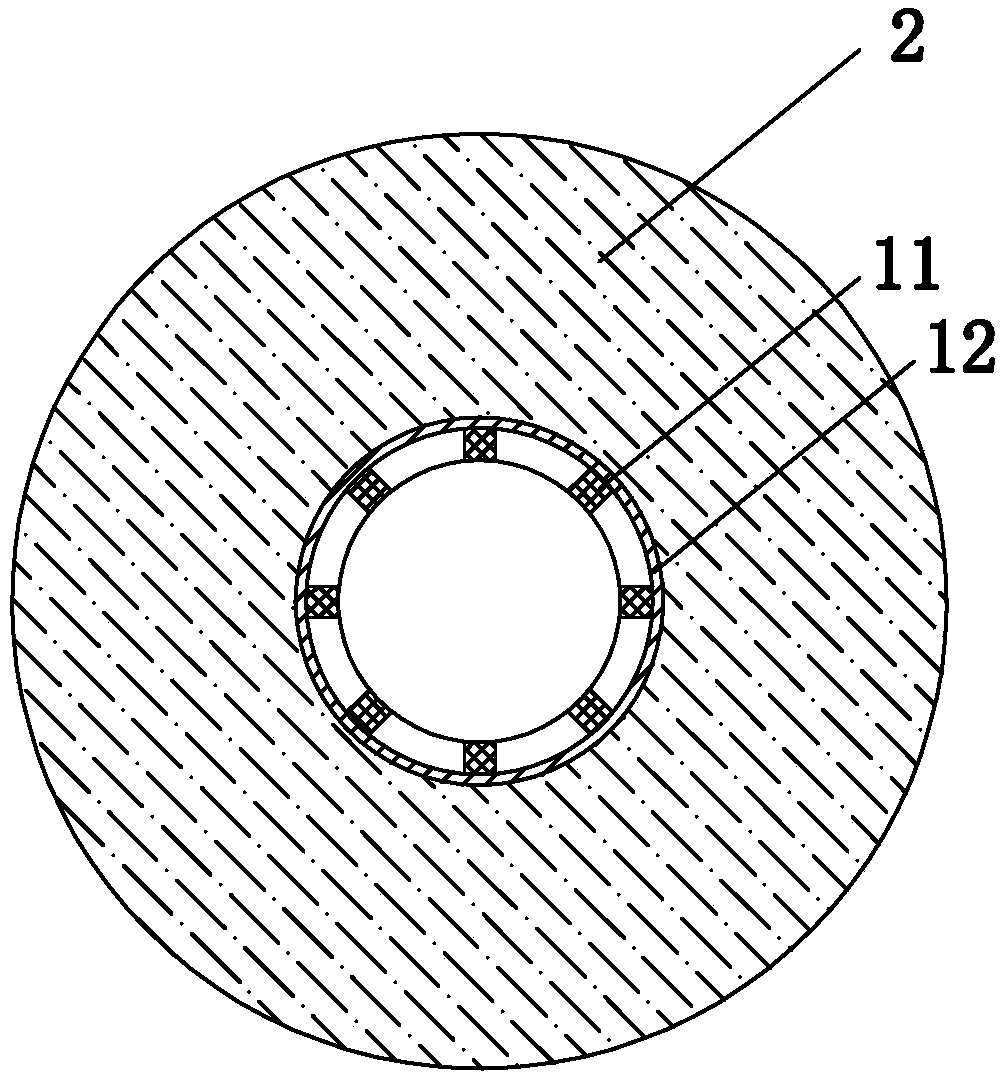
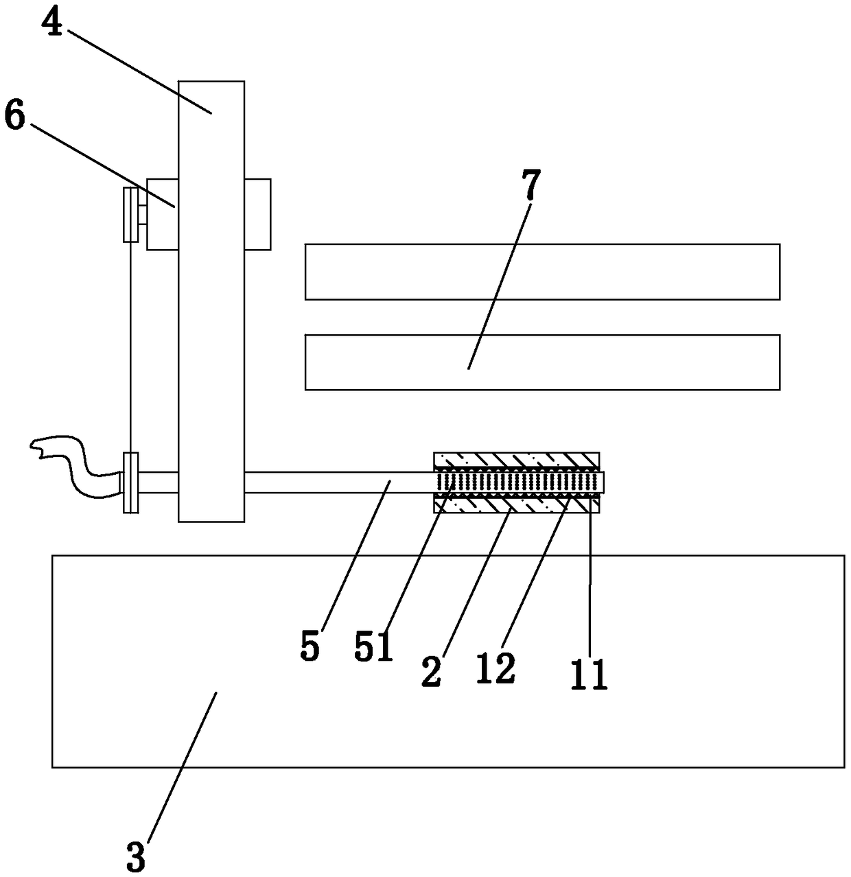
[0019] figure 1 As shown, the present embodiment provides a ceramic fiber hollow filter rod, which includes a support skeleton tube and a filter material layer 2 sleeved outside the support skeleton tube. The support skeleton tube includes a skeleton tube 11 and is sleeved outside the skeleton tube 11 The non-woven fabric 12; the filter material layer 2 is composed of the following materials in parts by weight: 65 parts by weight of short aluminum fibers, 20 parts by weight of nanofibers, 15 parts by weight of diatomaceous earth, and 10 parts by weight of adhesive. The particle size of the diatomite is 100 mesh to 250 mesh. The binder is an inorganic binder.

[0020] The adhesive can be acrylic glue. The non-woven fabric is PET non-woven fabric. The skeleton tube is made of PP material, and a plurality of penetrating holes are arr...


PUM

PropertyMeasurementUnit
particle size (mesh)aaaaaaaaaa

Abstract

The invention relates to the field of filter cores, in particular to a ceramic nanofiber hollow filter rod comprising a supporting framework barrel and a filter material layer sleeving the supportingframework barrel. The filter material layer includes, by weight parts, 50-75 parts of short fiber aluminum fiber, 10-30 parts of nanofiber, 8-25 parts of diatomaceous earth and 5-15 parts of binder. According to the ceramic nanofiber hollow filter rod, the technical problem that a fiber-shaped material cannot be formed into a filter core in an existing mode is solved.

Description

technical field [0001] The invention relates to the field of filter cores, in particular to a ceramic nanofiber hollow filter rod. Background technique [0002] With the improvement of people's living standards, people have put forward higher requirements for the water quality of drinking water, and water purification filters have been widely welcomed. When the filter is used for water treatment, the decisive factor is the filter element. There are usually three types of existing filter elements. The first type is to simply mix several granular filter materials and then fill or connect them together through simple equipment, which cannot fully exert the purification function of various high-quality filter materials, and is prone to black Defects such as water and hardening; the second is to mix, stir, and extrude several granular materials and rubber powder. This method is first of all very restrictive and only suitable for granular, powdery, and fibrous. The method is rea...

Claims


Application Information

Patent Timeline
Patent Type & Authority Applications(China)
IPC IPC(8): B01D39/14
CPCB01D39/14B01D2239/025B01D2239/0407B01D2239/0421B01D2239/10
Inventor 汤志文
Owner 福建滤冠新型材料科技有限公司
Learn More