Automatic discharging device of upper discharge centrifugal machine

A technology of automatic discharging device and centrifuge, which is applied in the direction of centrifuge, etc., can solve the problems of low discharging efficiency, labor and labor, cost waste, etc., and achieve the effect of improving the degree of automation, increasing the discharging efficiency and avoiding cost waste

Pending Publication Date: 2019-02-22
JIANGSU PEONY CENTRIFUGE MFG
View PDF0 Cites 0 Cited by
  • Summary
  • Abstract
  • Description
  • Claims
  • Application Information

AI Technical Summary

Problems solved by technology

[0002] A centrifuge is a machine that uses centrifugal force to separate components in a mixture of liquid and solid particles or liquid and liquid. The centrifuge is mainly used to separate the solid particles in the suspension from the liquid, or to separate the two densities in the emulsion. , and separate immiscible liquids (such as separating cream from milk); it can also be used to remove liquid from wet solids, such as drying wet clothes with a washing machine; special super-speed tube separators can also separate different densities gas mixture; using the characteristics of different sedimentation speeds of solid particles of different densities or particle sizes in liquids, some decanter centrifuges can also classify solid particles according

Method used


Image

  • Automatic discharging device of upper discharge centrifugal machine
  • Automatic discharging device of upper discharge centrifugal machine
  • Automatic discharging device of upper discharge centrifugal machine

Examples


Example Embodiment

[0019] The technical solutions in the embodiments of the present invention will be clearly and completely described below in conjunction with the accompanying drawings in the embodiments of the present invention. Obviously, the described embodiments are only a part of the embodiments of the present invention, rather than all the embodiments. Based on the embodiments of the present invention, all other embodiments obtained by those of ordinary skill in the art without creative work shall fall within the protection scope of the present invention.
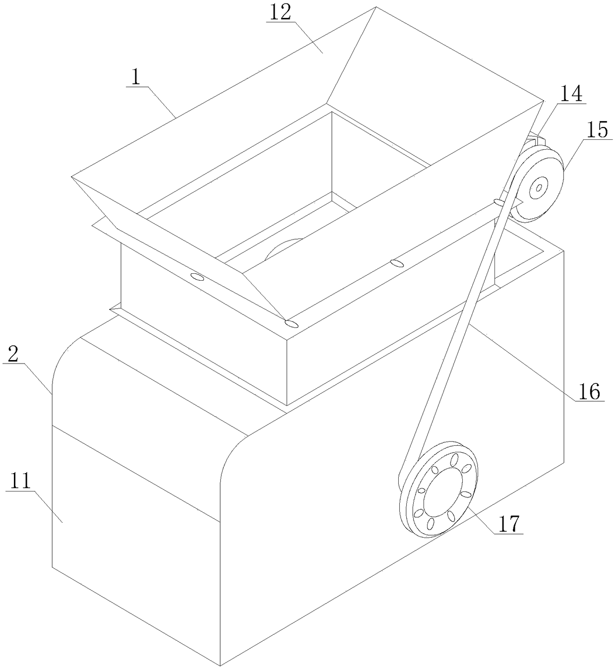
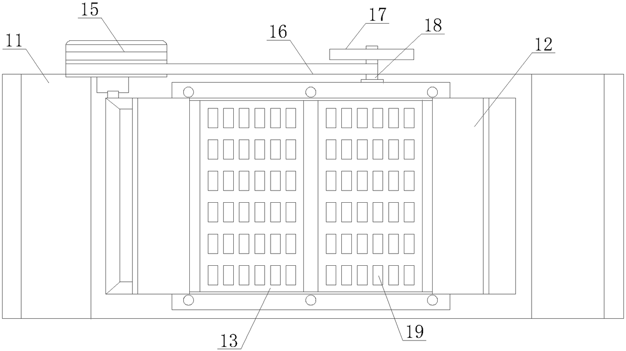
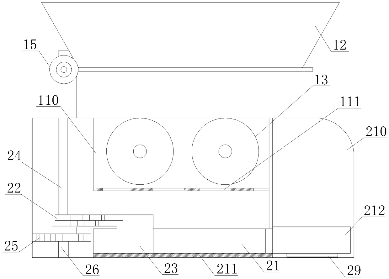
[0020] See Figure 1-7 , An automatic discharging device of an upper unloading centrifuge, comprising a centrifugal mechanism 1, a discharging mechanism 2 and a control mechanism 3. The discharging mechanism 2 is installed under the centrifugal mechanism 1, and the discharging mechanism 2 is controlled by the control mechanism 3. The mechanism 1 includes a chassis 11, a feeding port 12, a centrifugal tank 13, a motor fixing member 14, a ...


PUM


Abstract

The invention discloses an automatic discharging device of an upper discharge centrifugal machine. The automatic discharging device comprises a centrifugal mechanism, a discharging mechanism and a control mechanism. Centrifugal materials enter centrifugal tanks from a feeding opening, the centrifugal tanks carry out rotating centrifugation, liquid obtained after centrifugation is discharged out from liquid outlet holes, and solid materials obtained after centrifugation fall into a bearing trough through a falling trough; the solid materials are pushed into a discharging trough through left-and-right sliding of thin-walled discharging plates; after a gravity inductor inducts that the gravity reaches the limiting value, a discharging sensor controls discharging shovels to stop moving; a lifting sensor jacks out the discharging trough upwards after receiving a lifting signal; and the solid materials obtained after centrifugation can be taken out from a discharging opening. By means of thedevice, the solid materials in the bearing trough are prevented from being accumulated, no-dead-corner discharging of the bearing trough is achieved, the discharging efficiency is increased, automation of the discharging process is achieved, and the automation degree of the device is increased; and compared with manual discharging, the workloads of workers are reduced, the situation that cost iswasted due to the fact that a large number of discharging workers are employed is avoided, and practicality is higher.

Description

technical field [0001] The invention relates to the technical field of automatic centrifuge discharge, in particular to an automatic discharge device for an upper discharge centrifuge. Background technique [0002] A centrifuge is a machine that uses centrifugal force to separate components in a mixture of liquid and solid particles or liquid and liquid. The centrifuge is mainly used to separate the solid particles in the suspension from the liquid, or to separate the two densities in the emulsion. , and separate immiscible liquids (such as separating cream from milk); it can also be used to remove liquid from wet solids, such as drying wet clothes with a washing machine; special super-speed tube separators can also separate different densities gas mixture; using the characteristics of different sedimentation speeds of solid particles of different densities or particle sizes in liquids, some decanter centrifuges can also classify solid particles according to density or parti...

Claims


Application Information

Patent Timeline
IPC IPC(8): B04B11/04
CPCB04B11/04
Inventor 顾坤一张威李小东
Owner JIANGSU PEONY CENTRIFUGE MFG
Why Eureka
Try Eureka